
Remote thermometer

The circuit employs a closed-loop op amp configuration, which significantly reduces the output impedance, thus enhancing its ability to reject noise and providing stable temperature readings. The op amp's inherent offset voltage drift is utilized as a primary sensing mechanism, allowing for precise temperature measurement without the need for additional components, thus simplifying the design and reducing potential points of failure. The LTC1052 is specifically chosen for its low offset voltage and drift characteristics, ensuring that the amplified output is stable and reliable.
The diode bridge connection is a critical feature that allows for versatility in the circuit, enabling it to accommodate both positive and negative offsets from the op amp's output. This flexibility is essential for applications where the temperature range might vary or where the sensor might be subjected to different environmental conditions.
Calibration of the circuit is straightforward and involves adjusting two trim pots to ensure accurate readings at the specified temperature points. This process guarantees that the system can adapt to variations in component tolerances and environmental influences, thereby maintaining accuracy. The final output of the circuit is designed to provide a clear and precise indication of temperature, making it suitable for applications in environments where high noise levels may otherwise interfere with sensor performance.
Overall, this op amp-based temperature sensing circuit exemplifies a robust and efficient design that leverages the strengths of operational amplifiers to deliver reliable performance across a range of operating conditions. The careful consideration of components and configuration ensures that the circuit remains functional and accurate, fulfilling the requirements of various applications in the field of electronics.The low output impedance of a closed loop op amp gives ideal line-noise immunity, while the op amp's offset voltage drift provides a temperature sensor. Using the op amp in this way requires no external components and has the additional advantages of a hermetic package and unit-to-unit mechanical uniformity if replacement is ever required.
The op amp's offset drift is amplified to drive the meter by the LTC1052. The diode bridge connection allows either positive or negative op amp temperature sensor offsets to interface directly with the circuit. In this case, the circuit is arranged for a + 10°C to +40°C output, although other ranges are easily accommodated.
To calibrate this circuit, subject the op amp sensor to a +10°C environment and adjust the 10 °C trim for an appropriate meter indication. Next, place the op amp sensor in a +40°C environment and trim the 40° C adjustment for the proper reading.
Repeat this procedure until both points are fixed. Once calibrated, this circuit will typically provide accuracy within ± 20 C, even in high noise environments. 🔗 External reference
Related Circuits
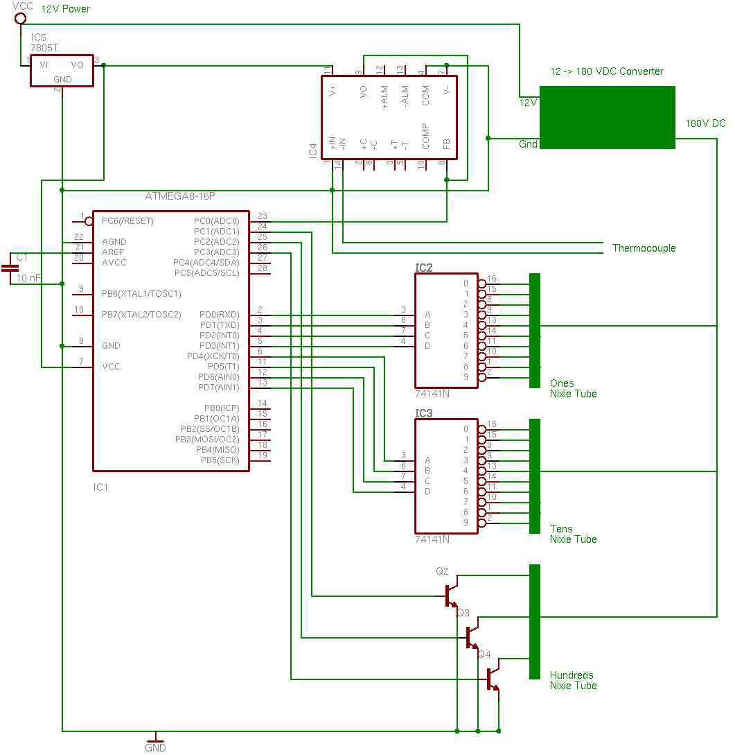
the entire circuit is comprised of integrated circuits. This makes for some easy organization when it goes to the circuit board for soldering. In addition, I used only 3 of the pins on the 3rd nixie tube for the...
This circuit allows for the control of any line-powered electrical device, such as a lamp, television, or fan, using any infrared remote control. Many individuals possess a collection of old IR remotes from appliances that are no longer in...
A radio remote control system utilizing DTMF (Dual-Tone Multi-Frequency) technology is presented. This circuit allows for the control of various electrical appliances through radio frequency signals. The described radio remote control system employs DTMF tones, which are generated by a...
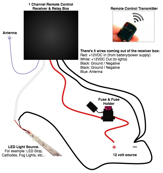
Installing a small dash-mounted two-speed fan in a motorhome. What is the best method? Use a one-channel relay or a four-channel relay with separate wires (one for low speed and one for high speed)? Any additional ideas? Would it...

A simple device that enables a quick check of common infrared remote controls can be beneficial for electronics enthusiasts often tasked with repairing or testing these widely used devices. A dependable circuit has been designed using a few components:...
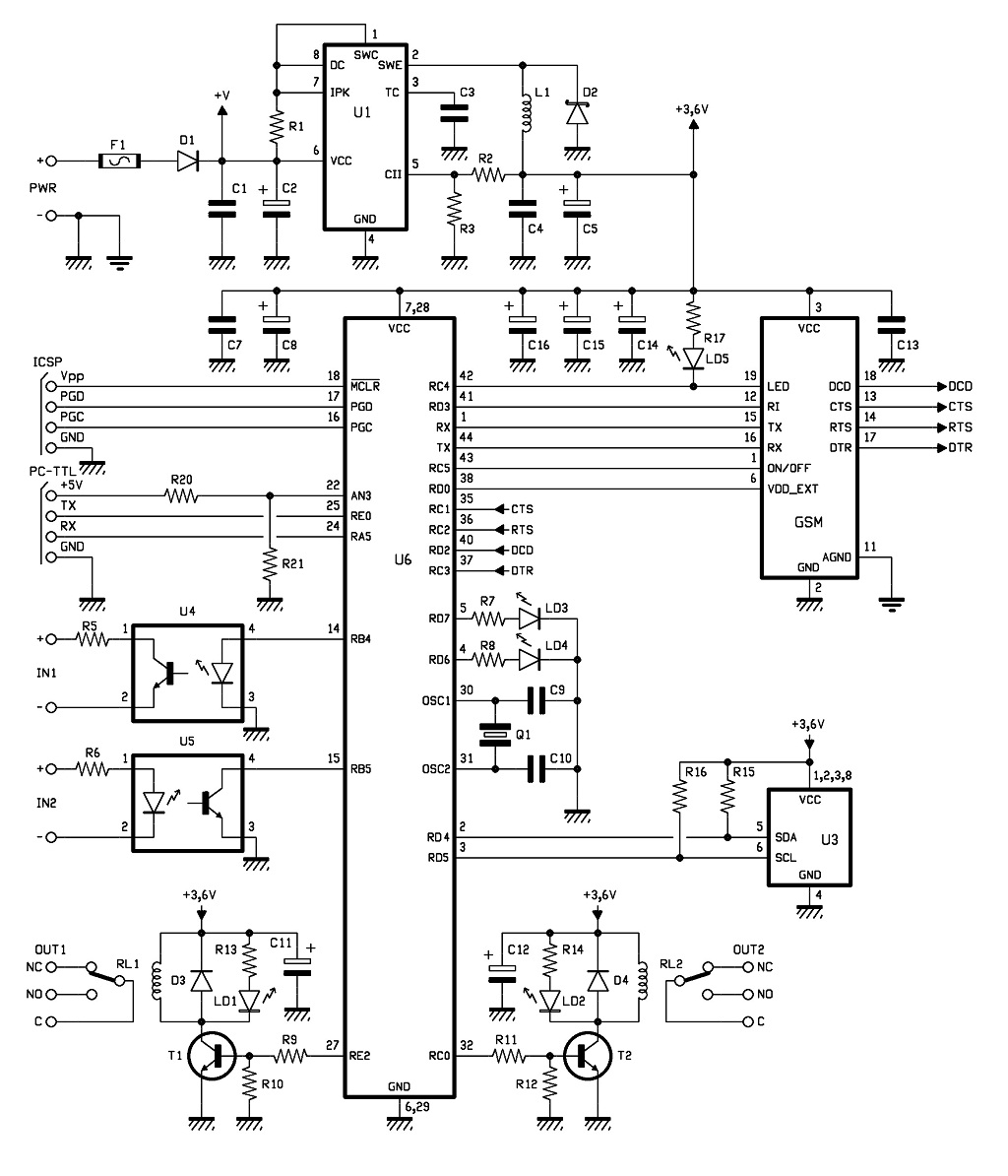
The control of the system is managed by a Microchip PIC18F46K20-I/PT microcontroller, which is programmed with firmware to oversee the activity of the GSM/GPRS module, monitor the logic conditions of two opto-isolated inputs, and send commands to two relays...