
RC Low-Pass passive Filter
The circuit described is a first-order low-pass filter, which serves to allow low-frequency signals to pass while attenuating high-frequency signals. The configuration consists of a resistor (R1) and a capacitor (C1) arranged in series. The output voltage (V(2)) is taken across the capacitor, while the input voltage (V(1)) is applied across the series combination of R1 and C1.
In this specific circuit, R1 is valued at 1 kΩ, and C1 is valued at 0.032 µF. The cut-off frequency (fc) can be calculated using the formula:
\[
f_c = \frac{1}{2\pi R C}
\]
Substituting the given values:
\[
f_c = \frac{1}{2\pi \times 1000 \, \Omega \times 0.032 \times 10^{-6} \, F} \approx 5 \, kHz
\]
This means that frequencies below 5 kHz will be allowed to pass with minimal attenuation, while frequencies above this threshold will be increasingly attenuated.
During the simulation, a sine wave generator is set to produce a 2 kHz signal, which falls below the cut-off frequency. As a result, this signal should appear at the output (V(2)), albeit with some minor amplitude reduction and a slight phase shift due to the reactive nature of the capacitor.
The transient analysis can be visualized in a SPICE simulator, where the input and output waveforms can be compared. Furthermore, an AC sweep analysis can be conducted to observe the filter's frequency response. This will provide a plot of the output magnitude (VM(2)) and phase (VP(2)) across a range of frequencies, illustrating how the filter attenuates signals above the cut-off frequency of 5 kHz. The expected behavior is that the output signal magnitude will remain relatively constant at low frequencies, while it will drop significantly as the frequency approaches and exceeds 5 kHz.What is the purpose of this circuit? Basically it has two roles: to pass the desired low frequency signals and stop the unwanted high frequency signals. Open the netlist file lpfilter1.cir” with your SPICE simulator. Most simulators display the netlist in a text editor window. You can view, modify and save the netlist from this window. Run a simulation. (TopSpice users click the traffic light on the toolbar; PSPICE users click the blue square.) View the transient (time) analysis at the input V(1) and output V(2).
For R1=1k, C1=0.032uF and sinewave generator at 2kHz, you should see the 2 kHz sinewave (desired signal) pass through to the output V(2) except for a slight decrease in signal and slight shift in time. As stated above, the circuit has two roles: to pass the desired low frequency signals and stop the unwanted high frequency signals.
But at what frequency does the filter change its behavior from passing the low ones to stopping the high ones. This is called the cut-off frequency. For R1=1k and C1=0.032uF you get fc = 5kHz. Run a simulation. Plot the AC (frequency) sweep results for the output magnitude VM(2) and phase VP(2). What does the magnitude look like before and after 5kHz? 🔗 External reference
Related Circuits
I keep all rights to those circuits myself. You may freely build those circuits to yourself and your friends, but commercial use of those circuits is not allowed. NOTE: Those circuits are old designs from time when I was...
A VU-meter is a common instrument typically found on audio Hi-Fi amplifiers, designed to display the instantaneous power delivered to the speakers. It is usually connected at the amplifier's output, in parallel with the speaker. The term "VU" stands...

A subsonic filter is primarily utilized in low-frequency technology. It is commonly employed to eliminate very low frequencies that can cause distortions in music recording or reproduction. A subsonic filter is an electronic circuit designed to attenuate frequencies below a...
This circuit is a variable audio bandpass filter that features a low cutoff adjustable from approximately 25 Hz to 700 Hz and a high cutoff adjustable from 2.5 kHz to over 20 kHz. The roll-off is set at 12...
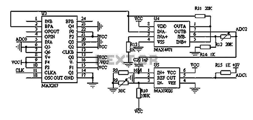
The filtering and amplifying circuit consists of two main components. The MAXIM MAX267 filter is an integrated circuit that can function as a low-pass, band-pass, high-pass filter, and other configurations, offering superior performance compared to traditional op-amp filters. The...
This circuit will filter out interference signals and ensure that the signal received from the Morse code station stands out. The described circuit functions as a signal processing system specifically designed to enhance the clarity of Morse code transmissions by...