
RC oscillator
Linear electronic oscillators are pivotal in generating sinusoidal signals for various applications, particularly in audio and communication systems. The Wien bridge oscillator is notable for its simplicity and effectiveness in producing low-frequency sine waves, making it an ideal choice for audio signal generation. The ability to tune the oscillator using variable capacitors or potentiometers allows for precise frequency adjustments, catering to specific audio requirements.
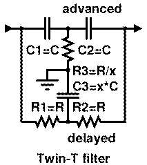
The Twin-T oscillator, with its unique configuration of low-pass and high-pass filters, provides a versatile solution for generating sine waves as well. Its design facilitates the cancellation of signals at the desired frequency, ensuring accurate oscillation without distortion. This configuration is especially useful in applications requiring stable frequency generation.
Amplitude control is a critical aspect of RC oscillators, as it ensures the output remains within a linear range, preventing distortion. The use of incandescent lamps or thermistors in feedback circuits exemplifies a practical approach to managing output levels. By adjusting the resistance based on temperature changes, these components effectively stabilize the oscillator's performance.
For applications where sine wave generation is not a necessity, alternative designs such as multivibrators or the 555 timer IC provide efficient solutions for generating square waves. These circuits typically require fewer components and are easier to implement, making them suitable for a wide range of electronic applications.
In summary, RC oscillators, including the Wien bridge and Twin-T configurations, are essential components in electronic design, offering flexibility in frequency generation and output stability across a variety of applications. Their ability to produce both sine and square waveforms makes them invaluable in the field of electronics.Linear electronic oscillator circuits, which generate a sinusoidal output signal, are composed of an amplifier and a frequency selective element,a filter. An oscillator circuit which uses an RC network, a combination of resistors and capacitors, for its frequency selective part is called an RC oscillator.
Two configurations are common. One is called a Wien bridge oscillator (pronounced `vEn and therefore often misspelled as "Wein Bridge"). In this circuit, two RC circuits are used, one with the RC components in series and one with the RC components in parallel. The Wien Bridge is often used in audio signal generators because it can be easily tuned using a two-section variable capacitor or a two section variable potentiometer (which is more easily obtained than a variable capacitor suitable for generation at low frequencies).
The archetypical HP 200 audio oscillator is a Wien Bridge oscillator. The second common design is called a "Twin-T" oscillator as it uses two "T" RC circuits operated in parallel. One circuit is an R-C-R "T" which acts as a low-pass filter. The second circuit is a C-R-C "T" which operates as a high-pass filter. Together, these circuits form a bridge which is tuned at the desired frequency of oscillation. The signal in the C-R-C branch of the Twin-T filter is advanced, in the R-C-R - delayed, so they may cancel one another for frequency If they are to produce an undistorted sine wave, RC oscillators usually require some form of amplitude control.
Many common designs simply use an incandescent lamp or a thermistor in the feedback circuit. These oscillators take advantage of the fact that the resistance of the tungsten filament of the lamp increases in proportion to its temperature, a thermistor works in a similar fashion. Operated well below the point at which the filament actually illuminates, increased amplitude of the feedback signal causes increased current flow in the filament thereby increasing the resistance of the filament.
The increased resistance of the filament reduces the feedback signal, limiting the oscillator`s signal to the linear range. (That is, clipping is prevented. ) The HP 200 oscillator introduced this technique. More-sophisticated oscillators measure the output level and use this as feedback to control the gain of the voltage-controlled amplifier within the oscillator.
If the amplitude detector has a flat frequency response, then this negative feedback of the amplitude measurement will ensure that the oscillator has a constant output amplitude no matter what frequency it is set to generate. Many designs exist for RC oscillators that are not required to produce a sine wave. Square waves are the most common. Multivibrators are one approach. The 555 timer IC is another very common approach. Most non-sine wave RC oscillators require only a single RC network. 🔗 External reference
Related Circuits
Common non-sinusoidal oscillator circuit, waveform and frequency formula - sawtooth oscillator - use multivibrator. The sawtooth oscillator is a type of non-sinusoidal waveform generator that produces a triangular or sawtooth-shaped output signal. This oscillator is commonly utilized in various applications,...
Rick Friedrich, a student of Bedini, demonstrates his setup and results, asserting that by transferring charge from one battery to another using a motor system, this configuration can achieve a net energy gain by harvesting energy from the environment. The...
The Hartley oscillator is an LC electronic oscillator that derives its feedback from a tapped coil in parallel with a capacitor, forming the tank circuit. While mutual coupling between the two coil segments is not a requirement, the circuit...
Zener diodes were utilized to derive a stabilized voltage for the Hartley oscillator. While sorting through a box of valves, suitable voltage stabilizer valves (CV287) were discovered. During this process, the ECC81 utilized in the local oscillator was noted...
This FM oscillator can be utilized for wireless audio, microphone, and part-15 applications where a stable frequency-modulated oscillator is required. The FM oscillator is an essential component in various communication systems, particularly in wireless audio transmission and microphone applications. It...
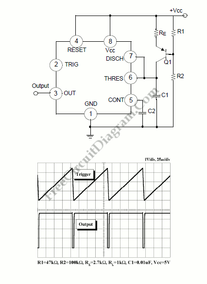
The voltage Vc1 increases linearly when the pull-up resistor RA in the monostable circuit is replaced with a constant current source, resulting in a linear ramp. The circuit for generating the linear ramp and the corresponding waveforms are illustrated...