
RCEN fuse bit blower for the AT90S1200 8Bit RISC CPU

The circuit described here is designed to activate the RCEN (RC oscillator ENable) fuse bit, which is non-volatile and remains set unless reprogrammed with different firmware. The circuit utilizes another AT90S1200 microprocessor as a master, which sends the necessary signals to the slave microprocessor (the one with the RCEN bit set). Extracting the required signal sequences from the datasheet was a complex task, taking considerable effort to understand and implement. The master microprocessor is connected to a crystal oscillator, allowing it to function without any special modes. The master socket can accommodate any AT90S1200 microprocessor (with or without the RCEN bit set) for software downloading using any serial programmer.
For powering the circuit, a +12V DC supply is recommended, which can be sourced from a low-cost power supply or a car battery, although caution is advised due to the potential risks of short-circuiting. The following steps outline the procedure for programming the microprocessors:
1. Insert the slave microprocessor into the master socket and download a test program using any compatible serial programmer. This program consists of a few commands that will make an LED connected to one of the ports flash, serving as an indicator to verify that the CPU can operate without a crystal. The flash memory storing the software in the AT90S1200 remains unaffected by the fuse bit setting.
2. After programming, remove the slave microprocessor from the master socket and place it in its dedicated socket at the bottom of the board. Insert another AT90S1200 microprocessor into the master socket for programming, which will remain unchanged and can be repurposed for other applications later. Download the software for the master, which contains the necessary instructions for signal transmission.
3. Remove Jumper 1, which disconnects the Reset pin of the slave from the control circuit of the master. This action releases the slave's Reset pin, allowing it to be pulled high by the internal pull-up resistor. Next, remove Jumper 2, which disconnects the master’s clock signal (driven by the crystal) from the slave's clock input. If the LED is already flashing, the RCEN bit in the slave has been successfully set, and the process can be halted at this point. If not, proceed to the next step.
4. Move Jumper 2 to the left position to establish the connection necessary for the programming process.
This comprehensive approach ensures that the internal oscillator is activated correctly, allowing for efficient operation of the AT90S1200 microprocessor in various applications.The AT90S1200 RISC Microprocessor (AVR family) is a very neat component to program a PLL synthesizer or for doing other rather trivial tasks in a radio circuit. It is reasonably cheap, easy to program and a nice integrated development environment is available for free from the manufacturer ATMEL.
And the best thing about it: It has an internal RC clock generator so it does not need a crystal, in fact it does not need any additional components at all. The internal oscillators frequency is somewhat temperature dependent, but for most applications it doesn`t really matter how fast exactly the processor works.
The only problem is that it is not possible to activate this internal oscillator with one of the (homemade or cheap-to-buy) serial in-circuit programmers. (The fusebits are only accessible in the parallel programming mode. ) Atmel sells a variant called AT90S1200A that has the internal oscillator activated by default. Unfortunately it seems to be impossible to get this variant here in Germany and from folks in the US I have learned that it is available but more expensive in the US.
The circuit published here is able to activate the so called RCEN (RC oscillator ENable) fuse bit which is non-volatile and will be set forever unless you put it in the circuits with another firmware to deactivate it. It uses another AT90S1200 (oh boy I love this smallest part of the AVR family) as a master that sends all the necessary signals to the slave (the one that has the RCEN bit set).
The hardest part was actually to extract all the necessary signal sequences from the datasheet. (It took me a full weekend to really understand everything and build the circuit. ) The master has a crystal attached so it works in no special mode or such. The master socket can also be used to plug in any AT90S1200 (RCEN set or not) to download software with any serial programmer. (If you don`t have one surf the net, there are lots and lots of ideas, I use a homemade one as described on the ATMEL page in application note 910.
) (Well, I would not claim that every step that is mentioned here is absolutely necessary. But if you do it like that, you will be in control of the situation at every point in time. ) For all coming steps I assume that the circuit is supplied with +12Volts DC. A cheap power supply will do, the circuit uses only a few milliamps. I use +13. 8V from my amateur radio power supply and it works fine for me. If you have no idea where to get +12V then use your cars battery but be careful, a short-circuit can be dangerous. 1. Plug in the slave in the master socket first and download the following test software (any serial programmer with the ATMEL defined plug can be used).
It consists of only a few commands that make a LED on one of the ports flash. We will use this later on as an indicator to check if the CPU is able to run without a crystal. (The flash memory that holds the software in a AT90S1200 is not affected by setting the fuse bit. ) 2. Take out the slave of the master socket and put it in its own socket at the bottom of the board. Then take another AT90S1200 and put it in the master socket. This one will not be changed in any way and can be used for other applications after the job is done. Download the software for the master. This is the one that contains the know-how on what kind of signals must be sent. 3. Remove Jumper 1, this cuts the connection between the Reset pin of the slave and the control circuit from the master.
So the slaves Reset pin is released and will be drawn to high by the internal pull-up resistor. Remove Jumper 2, this cuts the connection between the masters clock signal (driven by the crystal) and the slaves clock input. If the LED is flashing already then you can stop at this point, the RCEN bit in your slave is already set.
Usually nothing is happening now, so continue with step 4. 4. Put Jumper 2 in the left position, this establishes the connection 🔗 External reference
Related Circuits
This compact circuit is designed to eliminate the clutter of surplus small AC mains adapters from a desktop environment. The circuit functions as a smart DC power box. The circuit operates by consolidating multiple AC to DC power conversions into...
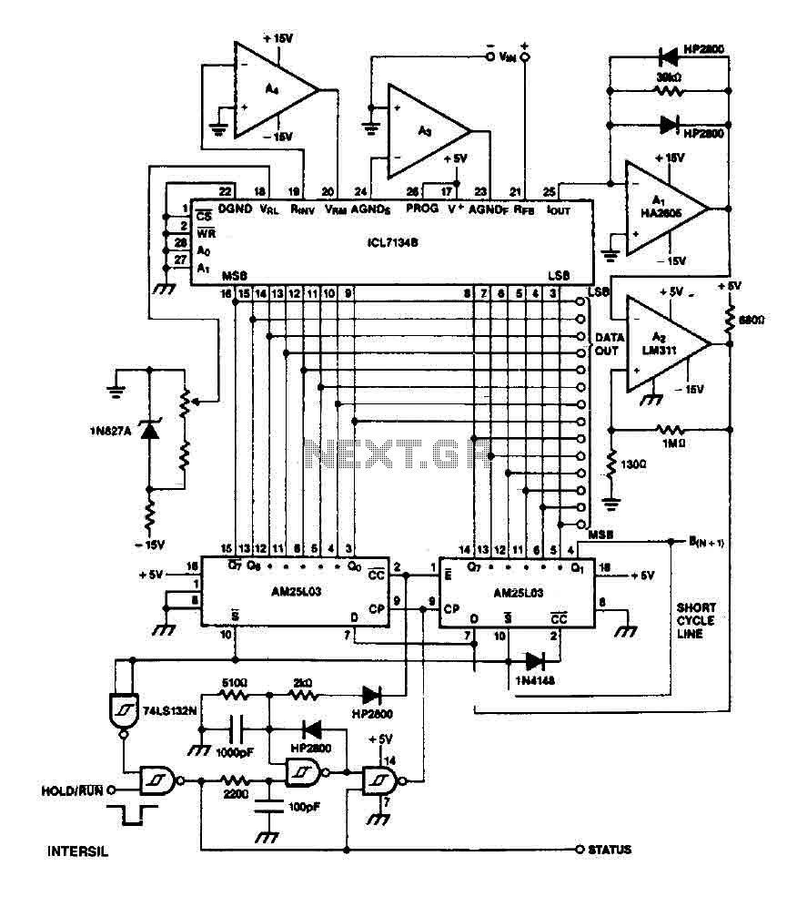
The ICL7134B circuit is a bipolar input analog-to-digital (A/D) converter that employs two AM25L03 chips to create a 14-bit successive approximation register. The comparator features a two-stage amplifier, HA2605, which is utilized to mitigate settling time issues at the...
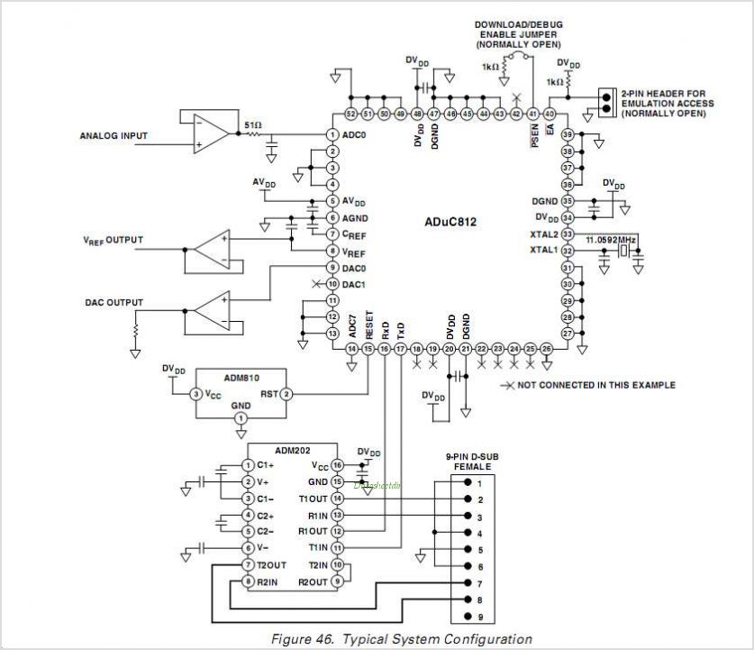
The ADUC814 MicroConverter is a fully integrated 12-bit data acquisition system-on-a-chip. Like all of ADI's MicroConverter products, it features precision A/D and D/A conversion along with a Flash Microcontroller on a single chip. The ADUC814 MicroConverter is designed to streamline...
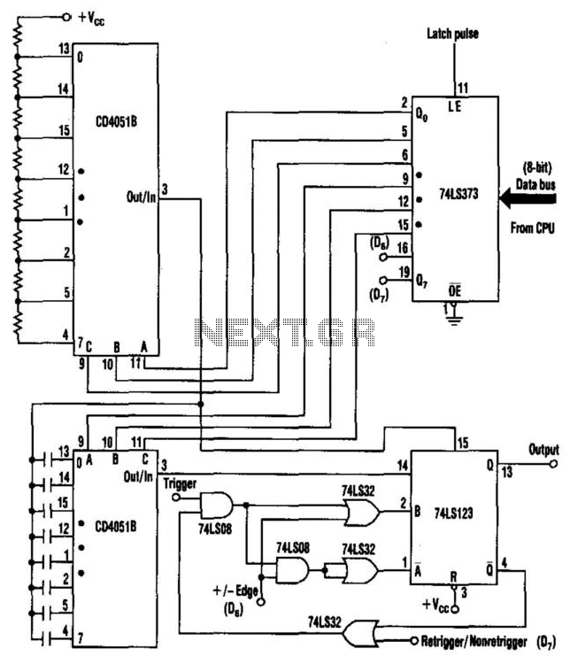
Process control applications often require a monostable multivibrator (one-shot) with a pulse width that can be selected on-the-fly. This circuit uses two CD4051B analog multiplexers to select the required timing components for the multivibrator, and hence, the pulse width....
This data sheet describes the evaluation board for the AD9834 direct digital synthesizer (DDS). The AD9834 is a numerically controlled oscillator that utilizes a phase accumulator, a sine look-up table, and a 10-bit DAC. The AD9834 can operate with...
The ADUC841, ADUC842, and ADUC843 are complete smart transducer front ends that integrate a high-performance self-calibrating multichannel ADC, a dual DAC, and an optimized single-cycle 20 MHz 8-bit MCU (compatible with the 8051 instruction set) on a single chip....
Warning: include(partials/cookie-banner.php): Failed to open stream: Permission denied in /var/www/html/nextgr/view-circuit.php on line 713
Warning: include(): Failed opening 'partials/cookie-banner.php' for inclusion (include_path='.:/usr/share/php') in /var/www/html/nextgr/view-circuit.php on line 713