
Receiver/Scanner Preamp Circuit
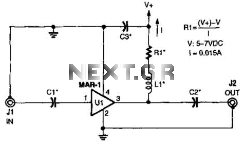
The Mini-Circuits MAR-X series is specifically designed for RF applications, making it an excellent choice for integrating into preamplifier circuits. The inherent 50-ohm impedance facilitates optimal matching in RF systems, minimizing signal reflection and maximizing power transfer. The MAR-1-based preamplifier circuit comprises several key components that work together to amplify weak RF signals effectively.
In the schematic, Ci and C2 play a crucial role in coupling and decoupling signals at different frequency ranges. The choice of capacitance values is critical; for high-frequency applications (HF), a 0.01 µF capacitor is utilized, while VHF applications typically require a 0.001 µF capacitor. For frequencies above 100 MHz, a 100 pF capacitor is recommended, allowing for flexibility in tuning the circuit to specific frequency ranges and ensuring optimal performance.
C3, as a ceramic disc capacitor, provides additional filtering and stability in the circuit. Its value can also be selected based on the desired frequency characteristics, with options of 0.01 µF or 0.001 µF. This selection aids in maintaining the integrity of the RF signal while minimizing noise and distortion.
Inductor L1, characterized as an RF choke, is essential for blocking high-frequency noise while allowing the desired RF signals to pass through. The inductance value, ranging from 0.1 to 10 µH, should be chosen according to the specific frequency range of interest. This component is crucial for maintaining the stability and performance of the preamplifier, ensuring that the amplified output remains clean and free from unwanted interference.
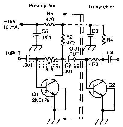
Overall, the MAR-1-based receiver/scanner preamplifier circuit, utilizing the Mini-Circuits MAR-X series components, is an effective solution for RF signal amplification, providing flexibility in component selection to accommodate various frequency ranges and applications. The low-cost Mini-Circuits MAR-X series of chips offer the RF builder a real advantage, with their inherent 50- input and output impedances (needed for RF systems). An MAR-1-based receiver/scanner preamplifier is shown. Ci and C2 are chip capacitors. Use 0.01 for HF, 0.001 for VHF, and 100 pF for above 100 MHz, depending on the low-frequency limit that you desire.
C3 can be a ceramic disc of 0.01 or 0.001, depending on frequency range. LI is an RF choke that is suitable for the frequency range that you desire (0.1 to 10uH). 🔗 External reference
Related Circuits
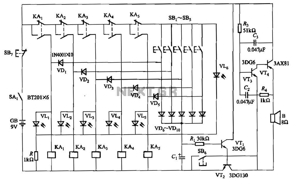
A relay-style circuit designed for a five electronic responder group. This circuit features self-locking capabilities, sound and light displays, time monitoring, and additional functions. The circuit includes a monitoring time button operated by the moderator. When this button is...
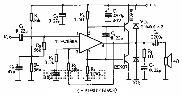
The rDA2030A TDA2030 is an enhanced version of the original product, with a maximum working voltage increased to 18V and a maximum output power of 18W. Additionally, harmonic distortion has been significantly reduced. The application circuit is illustrated. The rDA2030A...
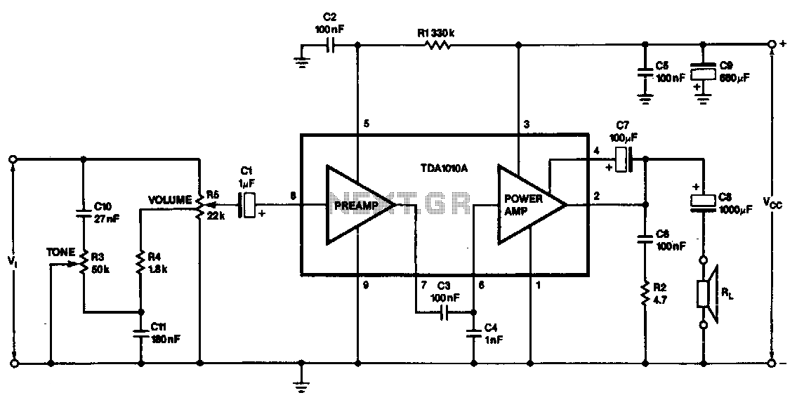
This monolithic IC, class-B audio amplifier circuit is a 6-W car radio amplifier for use with 4-ohm and 2-ohm load impedances. The monolithic integrated circuit (IC) described is designed to function as a Class-B audio amplifier, specifically tailored for...
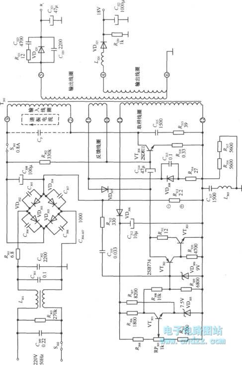
A high voltage switching stabilized voltage supply circuit is illustrated in the diagram. This is the switching power supply for an 80P type color television. It utilizes auto-excitation and a PWM circuit. The output is isolated from the power...
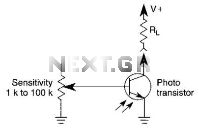
A variable resistor is utilized to adjust the light-level response of a phototransistor. Phototransistors exhibit higher light sensitivity compared to photodiodes; however, they typically demonstrate a lower frequency response. A variable resistor, often referred to as a potentiometer or rheostat,...
This simple, inexpensive, wideband RF amplifier provides 14 dB gain on two meters without the use of tuned circuits. The RF amplifier described operates within the two-meter band, which typically spans frequencies from 144 to 148 MHz. It is designed...