
Two-meter preamplifier

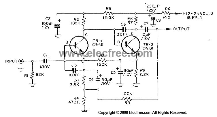
The RF amplifier described operates within the two-meter band, which typically spans frequencies from 144 to 148 MHz. It is designed to amplify radio frequency signals with a gain of 14 dB, making it suitable for applications such as amateur radio, signal boosting, and various communication systems. The term "wideband" indicates that the amplifier can operate effectively over a broad range of frequencies without requiring tuned circuits, which are commonly used in narrowband applications to select specific frequencies.
Key components of this RF amplifier may include transistors or integrated circuits that are capable of handling RF signals efficiently. The absence of tuned circuits simplifies the design, reducing component count and overall cost while enhancing reliability. The amplifier's performance can be further optimized through careful selection of passive components, such as resistors and capacitors, that determine the input and output impedance, stability, and frequency response.
The circuit layout should be designed to minimize parasitic capacitance and inductance, which can adversely affect performance at RF frequencies. Proper grounding techniques and the use of short, direct traces are essential to maintain signal integrity. Additionally, considerations for thermal management may be necessary to ensure the amplifier operates within its specified temperature range, as RF amplifiers can generate heat during operation.
Overall, this RF amplifier represents a practical solution for applications requiring moderate gain across a wide frequency range, offering an efficient and cost-effective means of enhancing signal strength in various RF communication systems.This simple, inexpensive, wideband rf amplifier provides 14 dB gain on two meters Without the use of tuned circuits.
Related Circuits
The preamplifier in question is engineered to interface with various audio devices such as CD players, tuners, and tape recorders. Its primary function is to provide an alternating current (AC) voltage gain of 4, an attribute that allows it to...
The circuit diagram of a guitar preamplifier is designed to accept any standard guitar pickup and features two signal outputs. A typical example of a pickup attached to a guitar headstock is illustrated. The pickup device consists of a...
This circuit utilizes three transistors (2SC945, 2C1815, or 2SC828) as the primary components, functioning as a typical low-noise transistor amplifier. It offers a gain of approximately 200 to 300 times and has a frequency response ranging from 50Hz to...
This circuit was submitted by Graham Maynard from Newtownabbey, Northern Ireland. It has an exceptionally fast high-frequency response, as demonstrated by applying a 100kHz square wave to the input. All graphs were produced using Tina Pro. The circuit in question...
The Software Defined Radio (SDR) hardware, in its most basic configuration, includes a wideband switched balanced mixer and a low noise LF amplifier. This straightforward hardware demonstrates remarkable sensitivity and linearity, making it suitable for both testing and regular...
The circuit was designed according to the RIAA implementation of a Hi-Fi phono preamplifier for the purpose of reproducing audio from a moving magnet cartridge. The RIAA (Recording Industry Association of America) equalization curve is essential for the accurate playback...