
Recording Level Meter Circuit
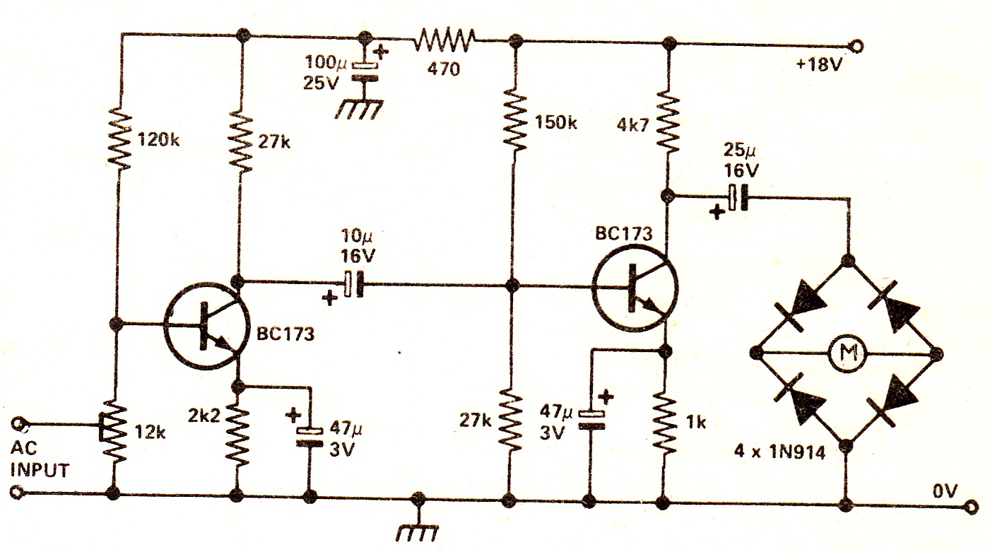
The described circuit employs a two-stage voltage amplification process to enhance an AC signal before it is converted to a DC voltage for display on a level meter. The first stage typically consists of a transistor or operational amplifier configured for voltage gain, while the second stage further amplifies the signal to ensure adequate drive capability for the meter.
The rectification stage is crucial as it converts the amplified AC signal into a DC voltage. This is often achieved using a diode bridge rectifier, which allows the circuit to respond to both positive and negative halves of the AC waveform, ensuring that the meter reflects the true level of the input signal.
The choice of a general-purpose meter provides flexibility, allowing for various applications within audio systems. The circuit's design facilitates integration with tape recorders or audio mixers, making it suitable for monitoring audio levels during recording or mixing processes.
The current consumption of 2.8 mA in a no-signal state indicates efficient power usage, essential for battery-operated devices or low-power applications. The inclusion of a 12 kΩ preset resistor enhances the circuit's versatility, enabling users to adjust sensitivity according to their specific requirements, which is particularly beneficial when working with different types of audio signals or varying input levels.
Overall, this circuit design is a practical solution for audio level monitoring, combining effective amplification and rectification while maintaining low power consumption and adaptability for various audio applications.The circuit shows a two ”stage voltage amplifier driving a recording level meter. The AC signal input is amplified, rectified, and the resultant DC voltage shown on the meter. The circuit can be used with a tape recorder or audio mixer and should be fed from a point early in the pre-amp. Current consumption in a no-signal state is 2. 8mA. The 12K preset gives a variation in sensitivity. The meter can be any general purpose type. 🔗 External reference
Related Circuits
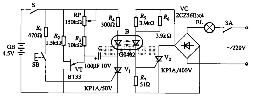
The circuit illustrated in Figure 2-48 consists of two configurations. Configuration 2-48 (a) operates using a 4.5V battery, while configuration 2-48 (b) employs AC capacitors to reduce the voltage supply. In configuration 2-48 (a), the delay time is influenced...
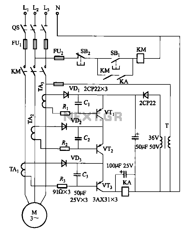
Drawing transistors that comprise the gate VTi, VT2, VT3, and similar components. The schematic involves a configuration of transistors designated as VTi, VT2, and VT3, which are integral to forming a gate structure. These transistors are typically arranged in a...
This circuit can be utilized in various devices to extract residual energy from seemingly depleted batteries. It is possible to connect multiple dead batteries in order to maximize energy extraction. This circuit design, often referred to as a Joule Thief,...
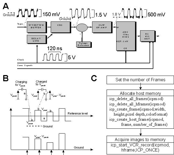
This document provides technical details regarding the hardware and software of a complete imaging system that utilizes a fast CCD sensor and a 41 Msample/s A/D converter. This system is capable of acquiring full-frame digitized images at a resolution...
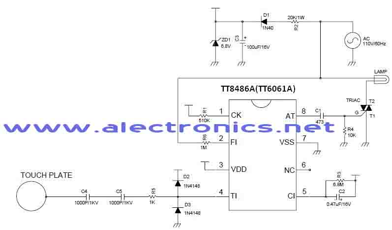
A simple dimmer circuit can be constructed using the CMOS ICs TT8486A and TT6061A, allowing control over the intensity of an incandescent lamp through a touch contact. This electronic touch dimmer can increase the brightness of incandescent lamps in...
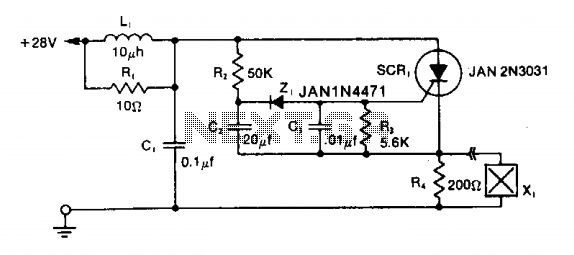
The LRC input network limits the anode dv/dt to a safe value below 30 V/μs. Rl provides critical damping to prevent voltage overshoot. While a simple RC filter section could be used, the high current required by the squib...