
TT6061A and TT8486A sensitive touch light dimmer circuit with explanation

This touch-sensitive dimmer circuit is a practical application of CMOS technology, utilizing the TT8486A and TT6061A integrated circuits to implement a user-friendly lighting control system. The design's simplicity lies in its minimal component count, enhancing reliability and reducing potential points of failure. The touch plate serves as an intuitive interface, enabling users to adjust lighting levels seamlessly without mechanical switches. The inclusion of capacitors C4 and C5 is crucial for ensuring user safety by isolating the high voltage from the touch plate, thus preventing electrical shocks.
The circuit's versatility allows it to be configured for different voltage levels, making it suitable for various applications in residential or commercial settings. The modifications for 220V operation highlight the adaptability of the design, accommodating different electrical standards while maintaining functionality. By adjusting resistor values and ensuring proper ratings for all components, the circuit can be safely and effectively utilized across different voltage systems.
In summary, this touch dimmer circuit exemplifies a blend of simplicity and functionality, making it an excellent choice for those seeking to enhance their lighting control capabilities with minimal complexity. The careful consideration of component ratings and configurations ensures both safety and performance, making this design suitable for a wide range of applications.Using a CMOS IC TT8486A TT6061A you can build a very simple dimmer circuit which can be used to control intensity of an incandescent lamb by simply touch a contact. This electronic touch dimmer circuit can increase the light intensity of incandescent lamps in three steps.
Initially, when mains switch is on, ` the bulb is off`. Now, if you touch th e touch plate, the bulb glows dimly. On second touch, the bulb gives medium light. At the third touch, the bulb is driven fully and another touch puts off the light. This sensitive touch light dimmer circuit uses minimum external components and can be used for 110V or 220V AC by simply changing some external components. For touch plate, you can use a simple copper plate of 1cmG—1cm (a small piece of PCB) or even the end of the lead wire.
Touch plate is coupled to the touch detector through 1000pF, 2kV capacitors C4, C5 connected in series. Internally IC TT6061A`s touch signal is connected to the counter/ decoder via a resistor and clock input CK is connected to the counter/decoder via a frequency generator.
This light dimmer circuit require a 6. 8 volts power supply, which is taken directly from mains through resistors R2, diode D1, capacitor C2, and zener diode and fed to power-input pin 3 of the IC. Capacitors C4, C5 connected between touch input pin 4 and touch plate remove the shock potential from the touch plate, so do not replace these capacitors with a single capacitor or with a capacitor of a lower voltage rating.
Te circuit diagram shown here is just for 110 volts ac, if you want to use this touch sensitivity light dimmer for 220 volts AC, you need to chance some components value. For 220 volts usage you`ll need to change R1 510K TO 620K ( FOR 60HZ CHANGE TO 50HZ ), R2 20K/1W TO 40K/2W ( FOR 110V CHANGE TO 220V ) and R6 1M TO 1.
5M ( FOR 110V CHANGE TO 220V ) and also you can add an additional capacitor in series with the C4 and C5 ( capacitor used must be the same type an value ). 🔗 External reference
Related Circuits
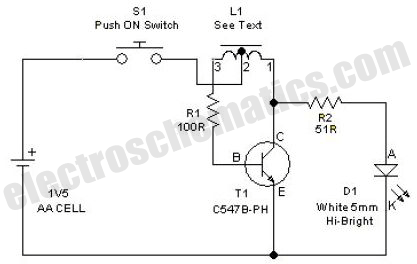
This simple LED driver circuit allows the operation of up to seven LEDs using a single NiMH (Nickel Metal Hydride) AA cell. The circuit generates voltage pulses. The LED driver circuit is designed to efficiently power multiple LEDs while maintaining...
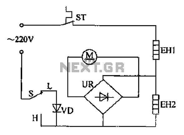
The comb electric circuit illustrated in Figure 1-3 features two temperature settings. By toggling switch S to either the L or H position, different temperatures can be achieved. Once switch S is activated, the circuit powers the heating wires...
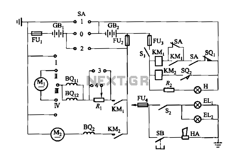
Denote cam controller SA 1 contact closure case. M1 is 1.35 kW driving motor, M2 is a 4 kW pump motor. The circuit involves a cam controller designated as SA 1, which is responsible for managing the operation of...
As the position of the sun changes, the illumination level on the light-dependent resistors (LDRs) also varies, causing the input voltage for the window comparator to deviate from half of the supply voltage. Consequently, the output of the comparator...
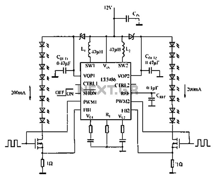
The automotive LED driver circuit diagram utilizes the LT3486. The LED is employed in the car's central high-mounted stop lamp (CHMSL), providing advantages such as faster achievement of the set brightness, higher efficiency, longer lifespan, and simplified design and...

The typical application circuit for the TDA1514A includes resistors R2 and R3, which form a feedback circuit to adjust their ratio, thereby creating an adjustable circuit loop gain. To enhance the dynamic range of the circuit, capacitors C5 and...