
ld168 audio control circuit diagram of a voltage-controlled flash decoration
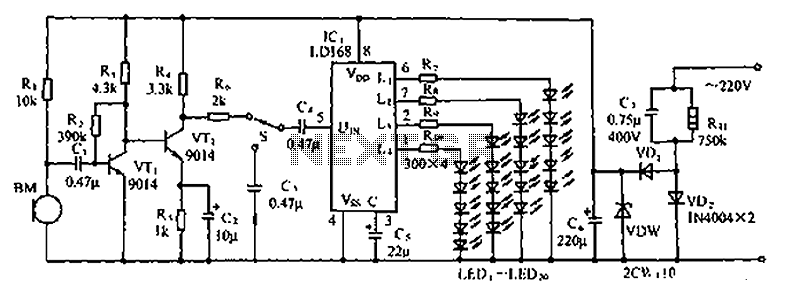
The LD168 circuit is designed to provide a visual representation of sound levels through the use of light-emitting diodes (LEDs). Each of the four outputs corresponds to different sound level thresholds, allowing for a clear indication of audio intensity. When the sound level reaches a specified point, the respective LED will illuminate, offering immediate feedback to the user regarding the audio output.
In terms of functionality, the LD168 can operate in two primary modes. The first mode utilizes direct LED drive, where the outputs are connected to the LEDs, allowing them to light up in response to the audio levels detected by the circuit. This mode is particularly useful in applications where real-time visual feedback is essential, such as in live sound environments or recording studios.
The second mode of operation involves the use of a thyristor drive, which enables the circuit to control higher power lantern lights. This feature is beneficial for applications that require more substantial lighting effects or where the use of standard LEDs would be insufficient. The thyristor acts as a switch, allowing the LD168 to handle higher voltage and current levels, thus expanding its usability in various settings.
Overall, the LD168 circuit is versatile and adaptable, making it suitable for a range of audio applications. Its ability to drive multiple outputs and integrate with different lighting technologies enhances its functionality, providing an effective solution for sound level indication. Circuit shown in Figure, LD168 is a flash of tape recorders speaker for sound level indication ASIC. It has four outputs can directly drive a plurality of light emitting diodes , the device can also be driven by lantern light emission thyristor drive.
Related Circuits
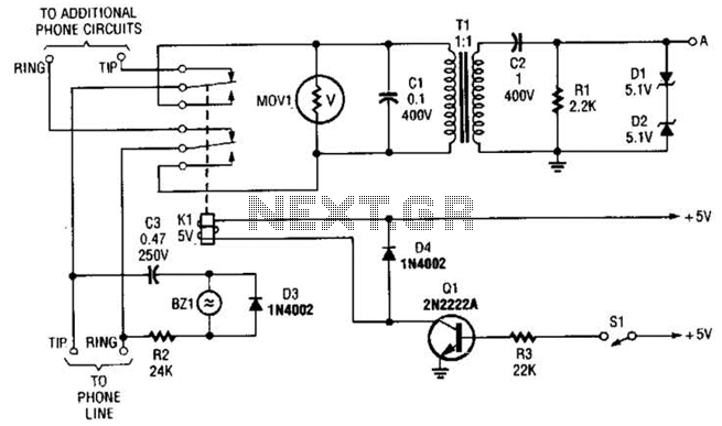
This circuit is designed for interfacing phone projects with the telephone line. It includes a ringer, has the capability to interrupt the wiring, and provides isolation for the project from the phone line. The circuit operates by integrating a ringer...
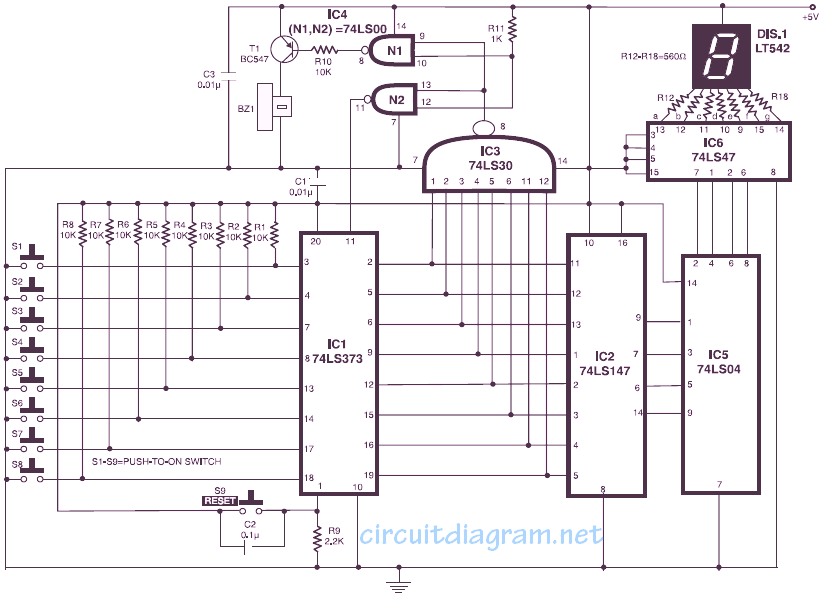
The circuit allows up to eight participants, each assigned a unique number from 1 to 8. The display indicates the number of the contestant who presses their button before the others. Simultaneously, a buzzer sounds. Both the display and...
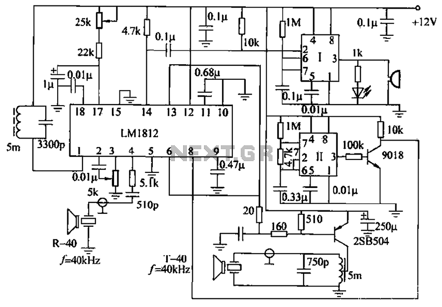
The ultrasonic anti-collision circuit is designed using the LM1812 integrated circuit, which controls both the transmission and reception functions. A distance control potentiometer allows for adjustments within a range of 2 to 3 meters. The timebase circuit is constructed...
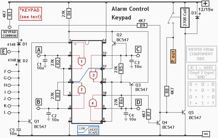
The integrated circuit (IC) is a quad 2-input "AND" gate, specifically a CMOS 4081. These gates output a HIGH signal only when both inputs are HIGH. When the key connected to pin E is pressed, current flows through resistor...
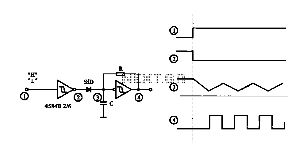
The circuit generates a controlled pulse signal. When a high pulse signal is applied to the input terminal O (start), the output pulse signal is activated. Conversely, when a low signal is received at the input terminal O (stop),...
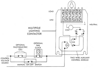
Sensors for lighting controls include photoelectric sensors and presence detectors. Photoelectric sensors typically switch lighting on at dusk and off at dawn, with adjustable settings for sensitivity to light levels. They feature built-in time delays to prevent unwanted switching...