
Regulated DC-to-DC converter
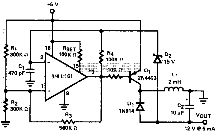
The described low power DC to DC converter employs a flyback topology, which is a popular choice for applications requiring isolation and voltage step-up capabilities. The square wave oscillator generates a pulsating signal that drives the primary winding of the transformer, creating a magnetic field. As the current in the primary winding increases, energy is stored in the magnetic core of the transformer.
When the square wave signal transitions from high to low, the magnetic field collapses, inducing a voltage in the secondary winding. The output voltage is then rectified and filtered to provide a stable DC output. The choice of a 20 kHz operating frequency is critical, as it balances the trade-offs between efficiency, component size, and electromagnetic interference (EMI). The lower frequency allows for the use of larger inductors and capacitors, which can be more efficient but may increase the physical size of the components.
The Zener diode (D2) plays a vital role in regulating the output voltage. It maintains a constant voltage level by shunting excess current when the output voltage exceeds a predetermined threshold. This ensures that the output remains stable within the specified limits, even as the load conditions change. The converter is designed to provide a maximum output current of 5 mA before it drops out of regulation, indicating that careful consideration must be given to load requirements to maintain performance.
Overall, the integration of the flyback circuit with a square wave oscillator in this low power DC to DC converter design allows for efficient voltage conversion while maintaining compactness and reliability in various electronic applications.Low power dc to dc converter obtained by adding a flyback circuit to a square wave oscillator. Operating frequency is 20 kHz to minimize the size of LI and C2. Regulation is achieved by zener diode D2 Maximum current available before the converter drops out of regulation is 5 mA. 🔗 External reference
Related Circuits
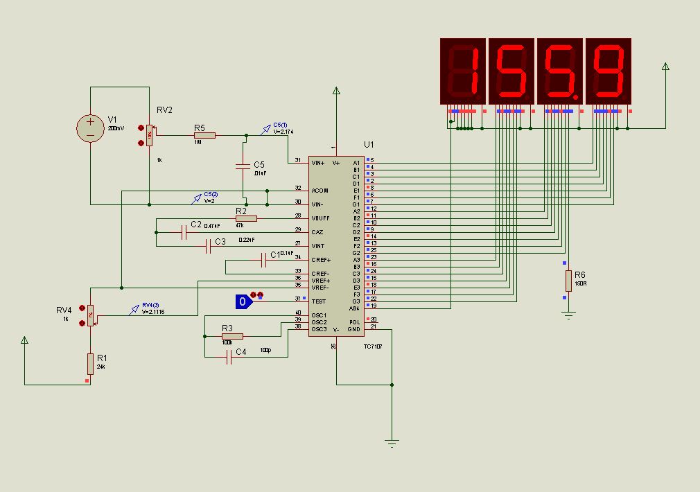
This document presents new models of a 3-digit common cathode (CC) and common anode (CA) multiplexed 3-digit voltmeter chip, specifically the TC7107 (ICL7107). It features a thumb switch with a common pin for BCD and hexadecimal outputs. The TC7107 is...
Switch-mode power supplies are utilized in electronic circuits to efficiently increase (step up) or decrease (step down) voltage levels. In comparison to linear voltage regulators, switch-mode supplies convert minimal energy into heat, resulting in high efficiency. This characteristic is...
The operation of the converter relies on the weighted addition and transfer of the analog input levels to the digital output levels. It comprises comparators and resistors. Although, theoretically, the number of bits is unlimited, each bit requires a...
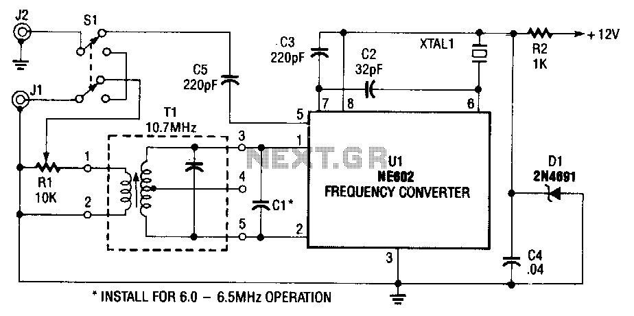
The NE602 (U1) includes oscillator and mixer stages. The mixer merges the oscillator signal with the input RF signal to generate signals whose frequencies are the sum and difference of the input frequencies. For instance, a 7.5-MHz signal received...
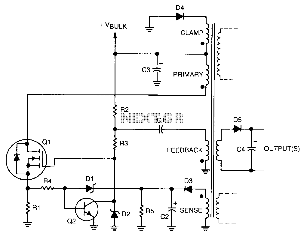
Regulation is achieved by using the rectified output from the sense winding, which is applied as a bias to the base of transistor Q2 through Zener diode D1. The collector of Q2 then disconnects the drive from the gate...

This is an adjustable and regulated power supply with an output voltage range of 3V to 30V and a current supply capability of up to 3A. This circuit is equipped with short circuit protection and overload protection. The adjustable power...