
4-Bit Analogue to Digital Converter
The electronic schematic for this converter can be constructed by integrating several key components that fulfill the outlined specifications. The core of the circuit consists of multiple comparators, each configured to compare the input analog voltage against a reference voltage, which is set to half the supply voltage. This reference voltage is generated using a voltage divider composed of two resistors, each valued at 10 kΩ, ensuring that the non-inverting inputs of the comparators are consistently at the desired threshold.
Resistors play a critical role in determining the weighting of the input signals. The values of these resistors must be chosen with precision to maintain the linearity of the converter. High-precision resistors should be utilized to minimize the effects of tolerance on the overall performance of the circuit. For applications requiring high accuracy, the TLC3074 comparator is recommended due to its favorable characteristics, including a totem-pole output configuration that enhances the drive capability.
To mitigate issues related to output loading, the output of each comparator can be buffered using CMOS inverters. Although these inverters typically have a lower gain, their high input resistance and low output resistance are beneficial in preserving signal integrity throughout the conversion process. Additionally, the circuit should be designed to ensure that the current draw remains within the specified limit of 5 mA, which is crucial for battery-operated or low-power applications.
In summary, the design of this analog-to-digital converter involves careful consideration of component selection, particularly resistors and comparators, as well as the implementation of appropriate buffering to achieve optimal performance and accuracy in converting analog signals to digital outputs.The operation of the converter is based on the weighted adding and transferring of the analogue input levels and the digital output levels. It consists of comparators and resistors. In theory, the number of bits is unlimited, but each bit needs a comparator and several coupling resistors.
The diagram shows a 4-bit version. The value of the resisto rs must meet the following criteria: The linearity of the converter depends on the degree of precision of the value of the resistors with respect to the resolution of the converter, and on the accuracy of the threshold voltage of the comparators. This threshold level must be equal, or nearly so, to half the supply voltage. Moreover, the comparators must have as low an output resistance as possible and as high an input resistance with respect to the load resistors as feasible.
Any deviation from these requirements affects the linearity of the converter adversely. If the value of the resistors is not too low, the use of inverters with an FET (field-effect transistor) input leads to a near-ideal situation. In the present converter, complementary metal-oxide semiconductor (CMOS) inverters are used, which, in spite of their low gain, give a reasonably good performance.
If standard comparators are used, take into account the output voltage range and make sure that the potential at their non-inverting inputs is set to half the supply voltage. If high accuracy is a must, comparators Type TLC3074 or similar should be used. This type has a totem-pole output. The non-inverting inputs should be interlinked and connected to the tap of a a divider consisting of two 10 k resistors across the supply lines.
It is essential that the converter is driven by a low-resistance source. If necessary, this can be arranged via a suitable op amp input buffer. The converter draws a current not exceeding 5 mA. 🔗 External reference
Related Circuits
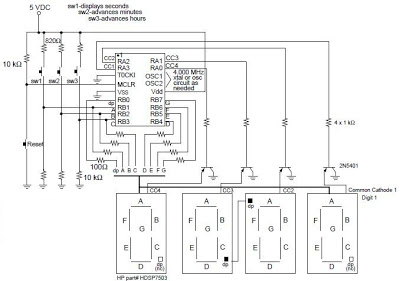
A digital clock project utilizing the PIC16C54 microcontroller can be constructed using the provided circuit diagram. This electronic project features a straightforward time-of-day clock that includes four seven-segment LED displays and three input switches, along with an additional reset...
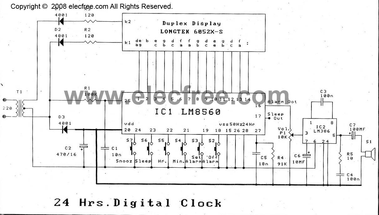
The digital time clock circuit is of great interest to electronic amateurs. The most popular clock ICs include the LM8361 and MM5387. Unfortunately, these ICs... The digital time clock circuit serves as an essential component for various electronic applications, providing...
This is a digital calendar circuit that utilizes a microcontroller to display the date, day, and month on an LED display. The entire system is managed by an 8-bit microcontroller, which operates based on a program embedded in its...
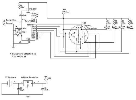
The digital navigation PC board may be configured for a number of navigation functions. It may be made into a simple visual digital compass, or a microcontroller based compass. The microcontroller based compass can be used for mobile robotics...
The reason why I am using an LCD display is because it allows me to display many characters and it doesn't need to be refreshed as 7-segment LED displays. Also, the interface requires less I/O pins. For this project,...
A 6V to 12V DC converter circuit is designed to convert a lower voltage of approximately 6 volts to a higher voltage of 12 volts, albeit with a reduced current rating. This inverter circuit can deliver up to 800mA...
Warning: include(partials/cookie-banner.php): Failed to open stream: Permission denied in /var/www/html/nextgr/view-circuit.php on line 713
Warning: include(): Failed opening 'partials/cookie-banner.php' for inclusion (include_path='.:/usr/share/php') in /var/www/html/nextgr/view-circuit.php on line 713