
Regulated dual power supply circuit from single battery source
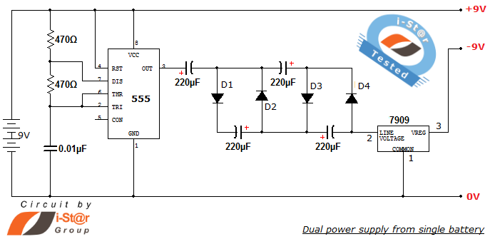
The dual power supply circuit described utilizes a single 9V battery to generate both positive and negative output voltages along with a ground reference. This configuration is crucial for applications that require dual polarity, such as operational amplifiers and audio preamplifiers. The NE555 timer IC operates in astable mode, producing a square wave output that can be used to drive the necessary components for voltage regulation and generation.
The circuit's design typically includes a pair of capacitors and resistors connected to the NE555 timer, which dictate the frequency of oscillation. By adjusting these components, the frequency can be tailored to meet specific application requirements. The output from the NE555 is then processed through a voltage regulator or a similar circuit to achieve the desired +9V and -9V outputs.
For customization, the circuit can be modified to generate other voltage levels, such as +5V, 0V, -5V or +12V, 0V, -12V, by selecting appropriate values for the voltage regulation components. The flexibility of the NE555 timer's operating voltage allows for a wide range of applications, ensuring that the dual power supply can be adapted to various experimental setups.
Overall, this dual power supply design is a practical solution for laboratory experiments requiring stable dual voltage levels from a single power source, facilitating a broad array of electronic applications.How to create dual power supply unit using single battery for your lab prupose Dual voltage power supplies are required particularly for op amp experiments and some of the instrumentation amplifiers. Some low power audio pre amplifiers also uses dual voltage supply. Here is a simple dual power supply schematic capable of producing +9V, 0V and -9V (dual polarity and ground potential) from a single 9V battery. You can create your own dual power supplies with different ranges of +Vcc and Vcc such as +5V, 0V and -5V or +12V, 0V and -12V. This article gives the working and constructional details of the circuit schematic using single battery source.
Timer IC NE555 is configured as a free running astable multivibrator oscillator. It provides approximately 100 kHz frequency. We have already discussed about astable multivibrator. The frequency of the astable multivibrator depends on the values of capacitor and resistorsassociatedwith 555 timer circuit. Our astable frequency calculator will help you decide them. The operating voltage of 555 timer IC isapproximatelybetween 3V to 16V, so by changing the battery supply you can implement required dual power supply varies from 3V to 16V other than +9V, 0V and -9V supply.
🔗 External reference
Related Circuits
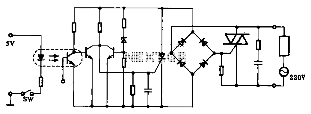
This application example illustrates a photovoltaic control circuit. In this circuit, the Triac functions as a solid-state relay, providing an AC power supply path to the load. It is designed to achieve high current control signals using a small...
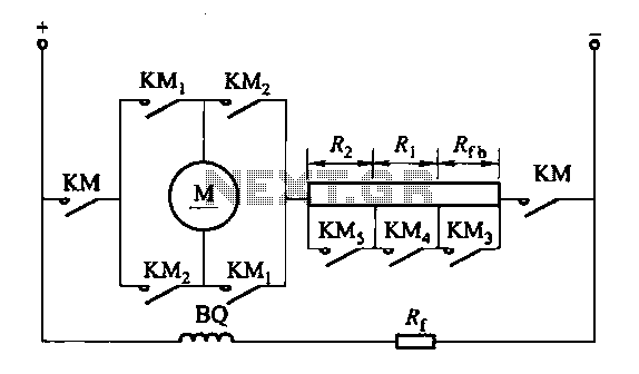
The circuit depicted in Figure 3-200 (a) illustrates the operation of a reverse braking system. When reverse braking is initiated, the forward contacts of contactor KMi open, and the reverse brake contactor KM3 disconnects while the reverse contactor KM2...
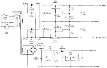
This bench power supply features three solid-state DC power supplies. The first supply provides an output of 1.5 to 15 volts at 1 ampere. The second supply offers a range of -1.5 to -15 volts at 1 ampere. The...
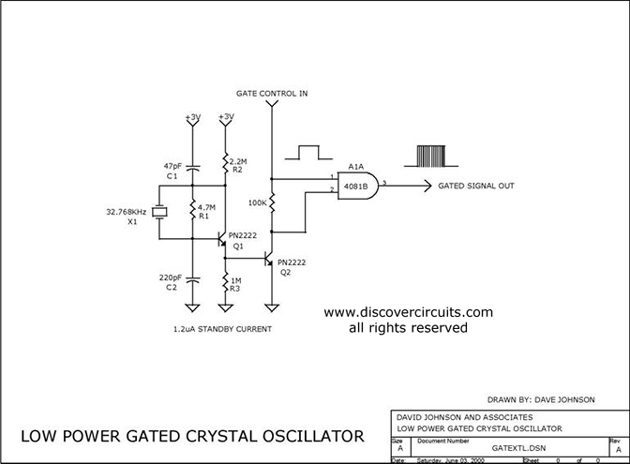
The circuit controls the output of a continuously operating 32KHz crystal oscillator, directing it to the input of a C-MOS buffer when clock pulses are required. This technique addresses the issue of a slow-starting crystal oscillator by maintaining the...
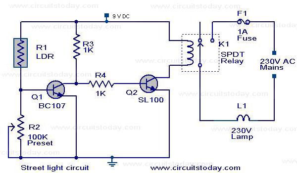
A street light that automatically switches ON when night falls and turns OFF when the sun rises. The circuit uses an LDR to sense the light. The automatic street light circuit functions by utilizing a Light Dependent Resistor (LDR) as...
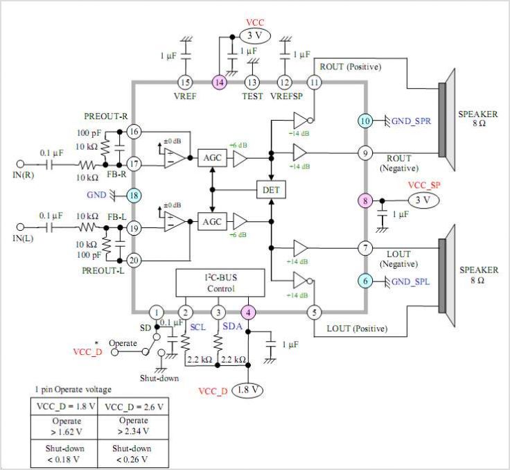
The AN41240A is a single-chip integrated circuit (IC) designed for audio applications. It employs a single-hall-sensor drive on the input side of the spindle motor drive block and utilizes a low-noise direct PWM drive of sine wave on the...