
Bench Power Supply I circuit diagram
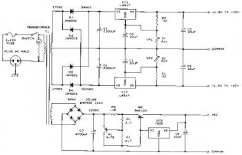
The bench power supply circuit consists of three independent solid-state DC power supplies, each designed to cater to different voltage and current requirements. The first power supply section utilizes a variable voltage regulator to provide an adjustable output from 1.5 to 15 volts, with a maximum current output of 1 ampere. This section is particularly useful for prototyping and testing circuits that require different working voltages.
The second power supply section is a negative voltage regulator that can output a range from -1.5 to -15 volts at 1 ampere. This negative supply is essential for applications that require dual-polarity power, such as operational amplifier circuits and analog signal processing.
The third power supply section provides a fixed output of 5 volts at 3 amperes, suitable for powering digital circuits and microcontrollers that typically operate at this voltage level. The fixed nature of this supply ensures a stable output for sensitive electronic devices.
All three power supplies are equipped with regulation circuits that utilize feedback mechanisms to ensure stable voltage outputs. The integrated circuit employed in the design plays a crucial role in maintaining the output voltage within 0.2 volts during load transitions, minimizing voltage fluctuations that could adversely affect connected devices.
Safety features are also an integral part of this power supply design. The output is protected against short circuits, preventing damage to the power supply and connected loads in the event of a fault condition.
The power supply requires a transformer to convert the AC mains voltage to the necessary levels for the DC conversion process. For regions operating on 120V AC, a transformer with a 17V AC center-tapped output is specified. Conversely, in areas with a 220-240V AC supply, a transformer rated for 18V AC center-tapped is recommended to ensure compatibility and safe operation.
This versatile bench power supply is well-suited for educational environments, electronics workshops, and any scenario where precise and reliable DC voltage sources are required.This benchpower supplyfeatures three solid-state DC power supplies. The first supply gives a 1. 5 to 15 volts at 1 ampere. The second supply gives a -1. 5 to -15 volts at 1 ampere. The third has a fixed 5V at 3 amperes. All DC supplies are fully regulated. A special IC circuit keeps the output voltage within. 2V when going from no load to 1 ampere . The output is fully protected from shortcircuits. This supply is ideal for use in school labs, service shops or anywhere a precise DC voltage is required. Take a note that based on the diagram, this circuit require 120V AC to 17V AC Center Tapped Transformer.
If your country use 220V AC home electric, you MUST change the Transformer 220-240V AC to 18V AC Center Tapped Transformer. We aim to transmit more information by carrying articles. Please send us an E-mail to wanghuali@hqew. net within 15 days if we are involved in the problems of article content, copyright or other problems.
We will delete it soon. 🔗 External reference
Related Circuits

An omnidirectional electret microphone is utilized to capture sound and convert it into an electrical signal. The output from the microphone is directed along two pathways. In the first pathway, the signal is routed to the inverting input at pin...
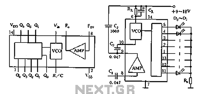
The circuit shown is a lighting control circuit that adjusts the speed of the flash output based on the strength of an audio signal. It utilizes eight flash integrated circuits (ICs) of the type LP188, which is housed in...
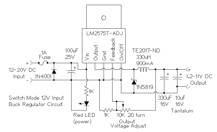
This is a simple buck mode switching regulator circuit diagram. This circuit is more efficient; switch mode regulators convert DC input voltage to pulses of high DC voltage. The DC pulses are used to charge a storage capacitor to...

Inverters U1a and U1b are connected in a simple RC oscillator circuit. The frequency is determined by the values of R1, C1, C2, and the internal characteristics of the integrated circuit. As long as the circuit is oscillating, a...
This circuit demonstrates how a low-drift preamplifier can enhance the measurement resolution of a thermocouple. The preamplifier is powered by the reference regulator, and bridge feedback is employed to bias the preamplifier input within its common mode range. Cold...

This circuit utilizes an "and other potential triggers" circuit. The term equipotential trigger refers to a crystal bidirectional thyristor trigger, which can be activated by either a positive or negative trigger. In this setup, the control electrode G and...