
A DC motor reverse brake circuit
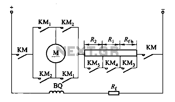
The circuit operates by utilizing multiple contactors and relays to manage the reverse braking process efficiently. When the operator engages the reverse braking mechanism, the system ensures that the forward motion is halted by opening the KMi contacts, which prevents any forward current from reaching the motor. Simultaneously, the KM3 contactor is deactivated, effectively isolating the forward drive circuit. The reverse contactor KM2 remains closed, allowing for the necessary current flow to facilitate reverse braking.
The reverse relay KA plays a critical role in this system. It monitors the operational state of the motor and ensures that the braking resistor Rf is introduced into the armature circuit during reverse braking. This resistor serves to dissipate energy generated during the braking process, thus protecting the motor from potential damage due to excessive back EMF. Once the motor speed diminishes to nearly zero, the circuit short-circuits the braking resistor to optimize performance and efficiency, allowing the motor to transition smoothly to a standstill without unnecessary energy loss.
The design stipulates that the resistance value R at the connection point for the KA relay coil should be carefully calculated. This ensures that the total resistance (Rq plus Rf) is halved, providing the correct conditions for the relay to activate reliably. The pickup voltage for the KA relay is set within a range of 0.4 to 0.45 times the supply voltage (Ue), allowing for consistent and dependable operation under varying load conditions. This specification is crucial for ensuring that the relay engages at the appropriate moment during the reverse braking sequence, thereby enhancing the overall safety and effectiveness of the braking system.FIG circuit 3-200 (a) in Fig. When the reverse brake, forward contacts open contacts KMi, reverse brake contactor KM3 contact is disconnected, reverse contactor KM2 contacts ar e closed. Tuning reverse relay KA line shown in Figure 3-200 (h). By reverse relay KA, when the reverse brake open when beginning to reverse braking resistor Rf access armature circuit; and when the brake to the motor speed approaches zero, the reverse braking resistor temple shorted. A connection point KA relay coil by R: resistance value is determined. A point should be the total resistance (Rq ten Rf) at half. KA relay pickup voltage setting in general (0. 4 ~ 0. 45) Ue.
Related Circuits
This circuit employs an astable multivibrator to alter the state of a signal based on specific conditions. It also incorporates a flip-flop, which retains the state of the output once a change is detected, completing a cycle of the...
Crystal 80mW FM transmitter circuit diagram of the production The Crystal 80mW FM transmitter circuit is designed to generate frequency modulated (FM) signals suitable for short-range audio transmission. This circuit primarily consists of a crystal oscillator, which serves as...
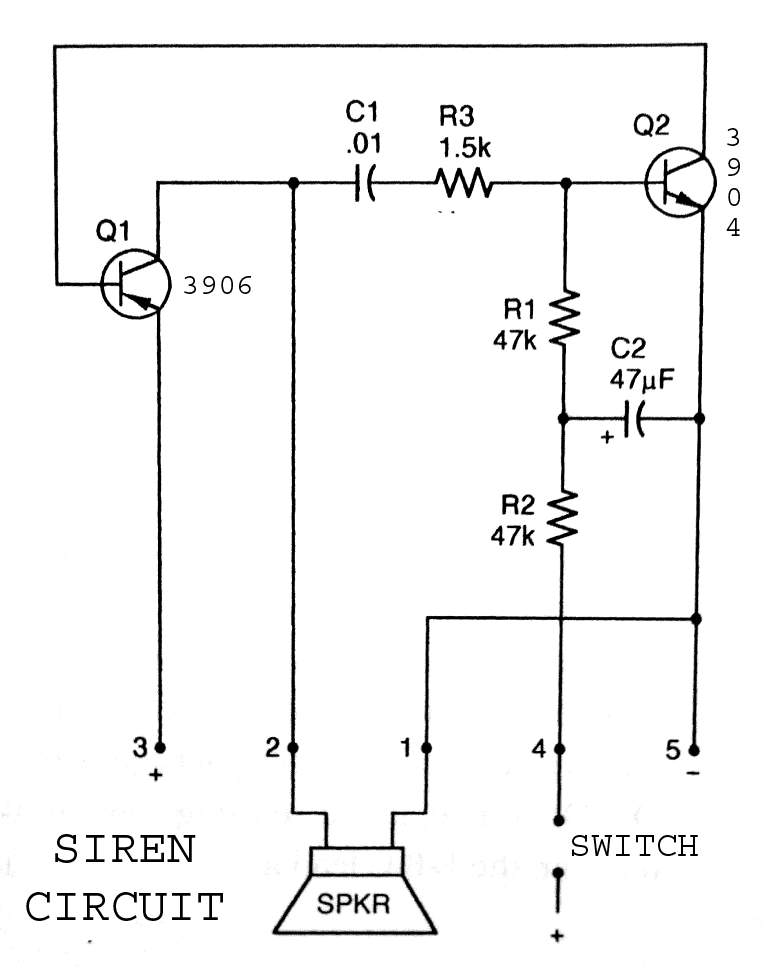
3904 3906 Siren Circuit. The circuit generates a wailing siren sound when the switch is activated. The 3904 3906 Siren Circuit is designed to produce a distinctive wailing sound, commonly used in alarm systems and signaling devices. The circuit utilizes...
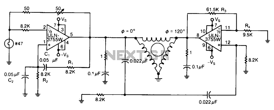
By varying either R1 or R2, the oscillator frequency can be adjusted over a narrow range. The R3/R4 ratio sets the second amplifier's gain to compensate for signal attenuation occurring in the phase shifters. The circuits can be driven...
The circuit consists of a capacitance three-point oscillator, an isolation level, a voltage doubler rectifier circuit, a stereo sound circuit, and a flash display circuit. It can detect the quality of a crystal; a good crystal will emit a...
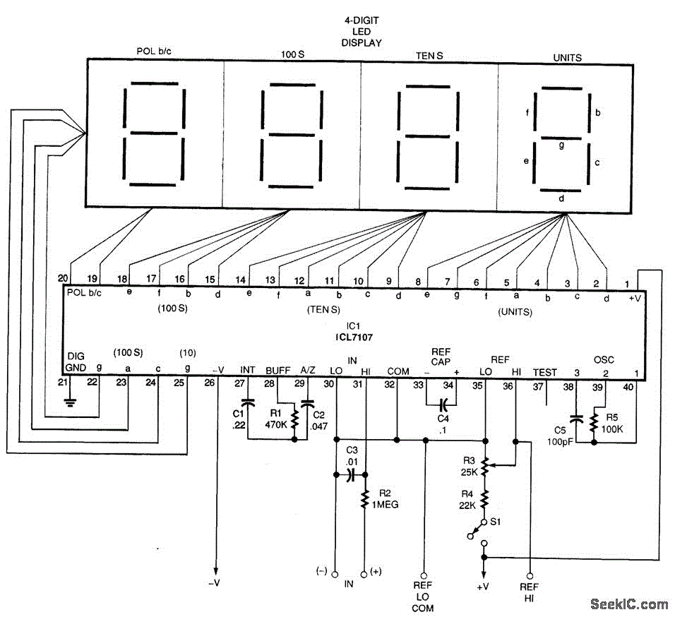
A basic digital voltmeter circuit utilizing the Harris Semiconductor ICL7107 is presented. It operates within a 2-V range. Calibration involves applying a known voltage of 1.2 V to the input and adjusting resistor R3 to achieve an accurate reading...
Warning: include(partials/cookie-banner.php): Failed to open stream: Permission denied in /var/www/html/nextgr/view-circuit.php on line 713
Warning: include(): Failed opening 'partials/cookie-banner.php' for inclusion (include_path='.:/usr/share/php') in /var/www/html/nextgr/view-circuit.php on line 713