
Regulated voltage divider
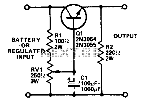
The circuit described utilizes a transistor as a linear voltage regulator to step down a higher voltage supply to the required 3 or 6 volts for powering integrated circuits. The configuration typically includes a voltage divider network or feedback mechanism to stabilize the output voltage. The transistor operates in the active region, where it regulates the output voltage while allowing for variations in load current.
The heatsink is a critical component in this design, as it dissipates the heat generated by the transistor during operation. The amount of power dissipated is a function of the voltage drop across the transistor and the current flowing through it. Therefore, selecting an appropriate heatsink based on the maximum expected power dissipation is essential to ensure reliable operation and prevent thermal failure.
The inclusion of capacitor C1 serves to smooth out voltage fluctuations at the output. The effectiveness of this filtering is enhanced by the transistor's gain, which effectively increases the capacitance seen at the output. This results in a significant reduction of ripple voltage, making the output more stable and suitable for sensitive IC applications.
The maximum output current capability of the circuit will depend on the specifications of both the power supply and the transistor selected. It is advisable to consult the datasheets for the chosen components to ensure they can handle the required load current while maintaining safe operating temperatures with the heatsink in place. Overall, this circuit design is a practical solution for powering low-voltage ICs from higher voltage sources while maintaining output stability and efficiency.ICs requiring 3 or 6 volts can be run from a battery or fixed regulated supply of a higher voltage by using the circuit shown. The transistor should be mounted on a heatsink as considerable power will be dissipated by its collector.
Additional filtering can be obtained by fitting a capacitor (Cl) as shown. The capacitance is effectively multiplied by the gain of the transistor, A ripple of 200 mV (peak to peak) at the input can be reduced to 2 mV in this fashion Maximum output current depends on the supply rating and transistor type (with heatsink) - used. 🔗 External reference
Related Circuits
This circuit inverts the polarity of the input. Output is limited to less than 200mA. More: U1 NE555 timer IC R1 1.2k ohm resistor R2 3.9k ohm resistor R3 1k ohm resistor C1 0.05 uF ceramic capacitor C2, C3...
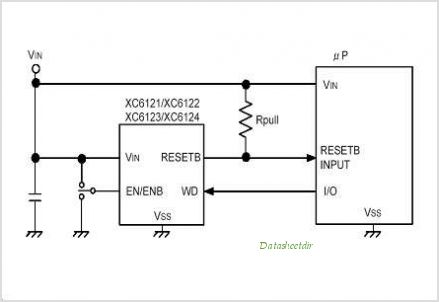
The XC61H series is a highly accurate, low power consumption CMOS voltage detector featuring a delay circuit. The detection voltage maintains high accuracy with minimal temperature drift. Output configurations are available in both CMOS and N-channel open drain. As...
This constant current constant voltage switched-mode power supply (SMPS) is designed for efficient battery charging. The circuit outputs a constant voltage of 7.2V and a constant current of 600mA. The operation mechanism is straightforward: when the load impedance is...
Power demand in portable designs can require, in specific applications, more than 1 A. A method involves paralleling two DC to DC converters on the same load instead of using a single higher current converter with a lower switching...
A keyed power input connector, series rectifier and a shunt rectifier, both 1N4007, prevent reverse voltage from being applied to the power input. A 27 volt metal oxide varistor clamps the voltage to the 78L05 that follow it, to...
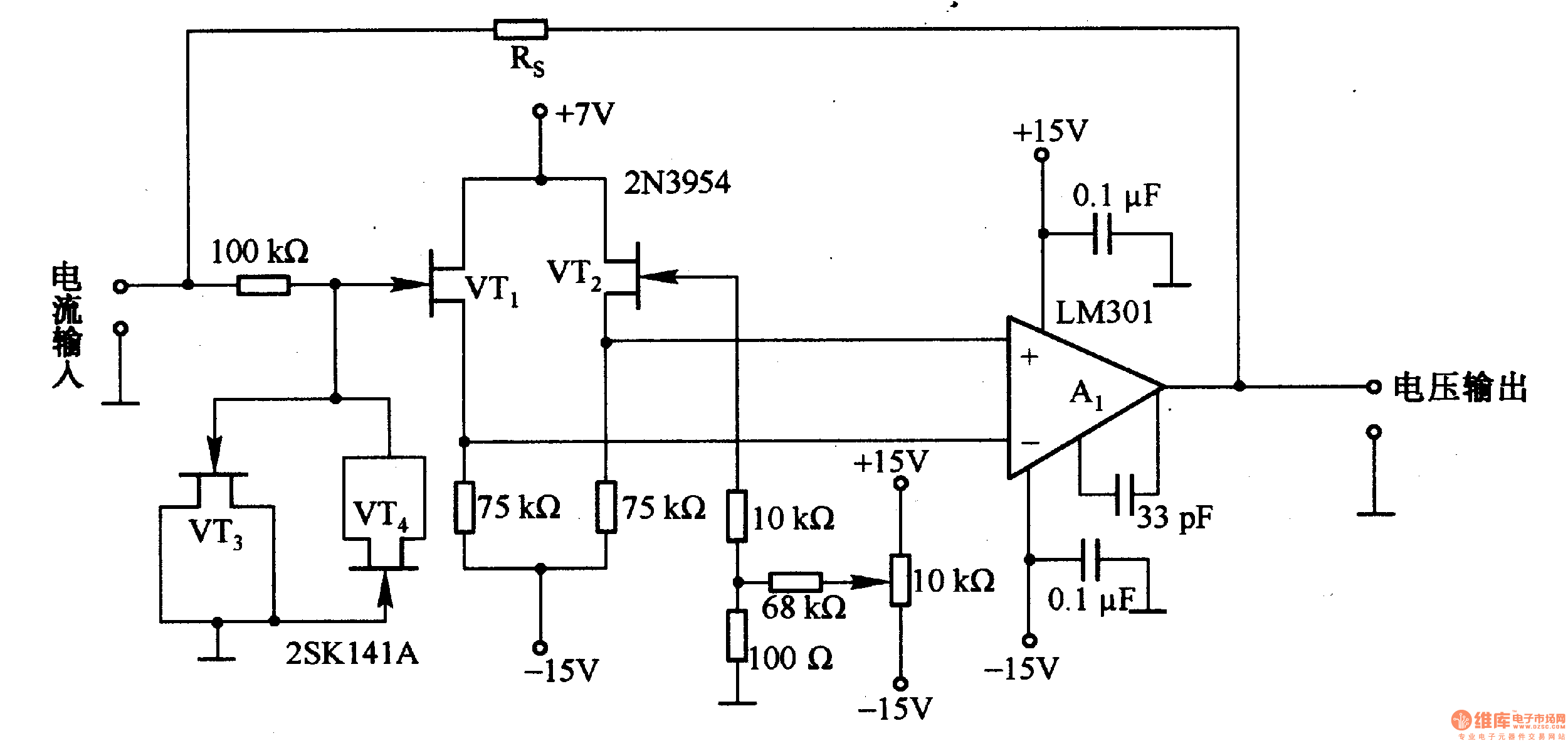
This is a low-input impedance conversion circuit with the reference resistor RS connected to the amplifier's feedback loop, resulting in an input impedance close to zero. The input current flows into the output end of the operational amplifier (Op-Amp)...
Warning: include(partials/cookie-banner.php): Failed to open stream: Permission denied in /var/www/html/nextgr/view-circuit.php on line 713
Warning: include(): Failed opening 'partials/cookie-banner.php' for inclusion (include_path='.:/usr/share/php') in /var/www/html/nextgr/view-circuit.php on line 713