Relay Output Proximity Sensor
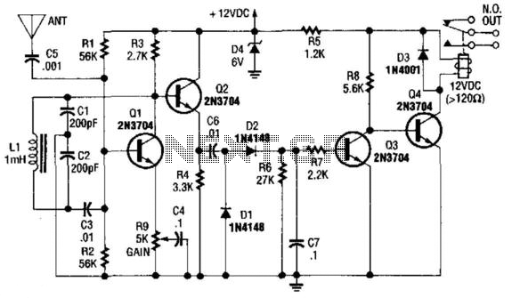
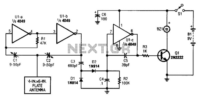
Q1 is used as an oscillator operating at approximately 300 kHz. Resistor R9 is configured to allow the oscillator to initiate its operation. An object near the antenna will load the circuit, causing the oscillations to cease. This change is detected by buffer Q2, diodes D1 and D2, which subsequently activates relay driver Q4, enabling the relay to operate.
The circuit utilizes a transistor Q1 configured as a Colpitts oscillator to generate a frequency of around 300 kHz. The frequency stability and oscillation initiation are influenced by the resistor R9, which is strategically chosen to set the threshold for oscillation. When the oscillator is active, it produces a consistent square wave output, which can be monitored.
The antenna is an essential component in this setup, as it is responsible for receiving external stimuli. When an object comes into proximity with the antenna, it introduces a capacitive load that alters the oscillation conditions. This loading effect results in a significant drop in the amplitude of the oscillation, ultimately leading to the cessation of oscillatory behavior.
To detect this change, buffer Q2 is employed, which serves to isolate the oscillator circuit from the detection circuitry while amplifying the signal for further processing. The diodes D1 and D2 are configured in a way that they respond to the reduction in oscillation amplitude, allowing them to provide a logic-level signal that indicates whether the oscillations are present or not.
Upon detection of the absence of oscillations, the signal is sent to relay driver Q4. This driver is designed to control a relay, which can be used to activate or deactivate other circuits or devices based on the presence or absence of the detected oscillation. The relay acts as a switch, enabling the system to perform a specific action, such as turning on a light or activating an alarm, when an object is detected near the antenna.
This circuit design is commonly used in proximity sensing applications, where the detection of nearby objects is crucial. The combination of the oscillator, detection circuitry, and relay driver allows for a reliable and effective means of object detection, which can be applied in various electronic systems. Ql is used as an oscillator around 300 kHz. R9 is set so that the oscillator just begins to run. An object ne ar the antenna will load the circuit down, and stop the oscillations. This is detected by buffer Q2, diodes Dl and D2, and this activates relay driver Q4, which operates the relay. 🔗 External reference

