
Magnetic Apogee Detection Sensor
A common misconception is that a mercury switch could be employed to detect this orientation more easily. A mercury switch relies on Earth's gravity as a reference and detects "down" based on the position of the mercury blob. The effects of gravitational acceleration when the rocket is on the launch pad and during flight are indistinguishable with a mercury switch. Once the rocket is launched, it no longer has Earth's gravity as a reference and will respond to any acceleration or deceleration. After the motor burns out, the rocket will begin to decelerate due to air resistance, but the mercury in the switch will continue moving. This behavior is analogous to turning the switch upside down while standing on the ground, leading the switch to believe it is inverted and triggering the ejection charge immediately after motor burnout, which is undesirable.
The Earth's magnetic field is independent of the rocket's speed or acceleration. To utilize the magnetic field as a reference, a sensor is required that outputs a voltage proportional to the angle of the sensor relative to the field, described by the equation V = Vmax cos θ. When this voltage falls below a specified reference, the ejection charge can be activated. To understand how such a magnetic apogee sensor operates, consider Figure 3, which depicts the relationship between the magnetic field and a rocket from a westward perspective. In this example, the magnetic field makes a 70-degree angle with respect to the horizontal, pointing down towards the north, a typical scenario in the northern United States. The rocket makes an angle θ with respect to the magnetic field. The magnetic apogee sensor is calibrated to trigger ejection when the magnetic field drops to zero (illustrated by the dashed line in the figure). This results in the ejection charge being activated at an angle dependent on the rocket's flight direction. To the south (left in Figure 3), ejection occurs when the rocket is pointed 20 degrees below horizontal; to the north (right in Figure 3), it occurs at 20 degrees above horizontal; and to the east or west, it is near horizontal.
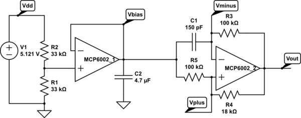
Several solid-state sensors are available for detecting magnetic fields, with the two most common types being based on the Hall effect or magnetoresistance. Most Hall effect sensors lack the sensitivity to detect the Earth's magnetic field of approximately 0.5 gauss; however, magnetoresistance (MR) sensors are capable of this detection. Two examples of MR sensors are the Honeywell HMC1001 and the Philips KMZ51. Data sheets for these components can be found online at Honeywell and Philips. Both devices function as MR Wheatstone bridges, outputting a voltage proportional to the magnetic field along the sensor's sensitive axis. The output voltages typically range from 5 to 15 mV/gauss. The output from one of these sensors must be offset and amplified to bring it into a useful voltage range. A schematic for a prototype magnetic apogee detection sensor is illustrated in Figure 4. This prototype is based on the HMC1001, with its output offset using resistors R2 or R3 and amplification stages to enhance the signal for further processing.
This design allows for accurate detection of the rocket's orientation relative to the Earth's magnetic field, enabling reliable triggering of the ejection mechanism at the appropriate time during the flight.Figure shows a simplified representation of the Earth`s dipole field, it resembles the field due to a bar magnet. The field lines originate at the south magnetic pole and terminate at the north magnetic pole. The angle that this field makes when it intersects the Earth`s surface is known as the inclination angle.
Figure 2 shows a contour plot of the inclination angle over the continental US. This angle varies from about 60 degrees in the south to about 75 degrees in the north. Since the magnetic field has a large vertical component, it is possible to use it as a reference to sense a rocket`s orientation and to set off an ejection charge when the rocket tips over at apogee. A common misconception is that a mercury switch could be used to detect this orientation more easily.
A mercury switch uses the Earth`s gravity as a reference and senses down with the blob of mercury. Acceleration due to gravity with the rocket sitting on the launch pad and accelerations while in flight are indistinguishable with the mercury switch. Once the rocket launches, it no longer has the Earth`s gravity as a reference and it will respond to any acceleration or deceleration.
After the motor burns out, the rocket will begin to decelerate due to air resistance but the mercury in the switch will keep on moving. This is the same behavior that turning the switch over while standing on the ground would have. In effect, this switch will believe it is upside down and will trigger an ejection charge immediately after motor burnout, not a desirable situation.
The Earth`s magnetic field is independent of the rocket`s speed or acceleration. In order to use the magnetic field as a reference, a sensor is desired that will output a voltage proportional to the angle of the sensor relative to the field, V=Vmax cos q. When this voltage falls below a given reference, the ejection charge could be triggered. To see how such a magnetic apogee sensor would function, consider Figure 3, which shows the relationship between the magnetic field and a rocket, as seen looking towards the west.
The magnetic field in this example makes an angle of 70 degrees with respect to horizontal pointing down towards the north, a typical situation in the northern US. The rocket makes an angle of q with respect to the magnetic field. The magnetic apogee sensor is adjusted to trigger ejection when the field drops to zero (the dashed line in the figure).
This results in then the ejection charge going off at an angle dependent on the rockets flight direction. To the south (to the left in Fig 3), ejection will occur when the rocket is pointed 20 degrees below horizontal, to the north (to the right in Fig 3), 20 degrees above horizontal and to the east or west, close to horizontal.
Several solid state sensors exist which can be used to detect magnetic fields. The two most common are based on the Hall effect or magnetoresistance. Most Hall effect sensors do not have the sensitivity to detect the 0. 5 gauss field of the Earth, however the magnetoresistance (MR) sensors do. Two examples of these MR sensors are the Honeywell HMC1001 and the Philips KMZ51. Data sheets for these devices are available online at: Honeywell and Philips. These two devices are both MR Wheatstone bridges which output a voltage proportional to the magnetic field along the sensitive axis of the sensor. The output voltages are typically 5-15 mV/gauss. The output from one of these sensors must be offset and amplified to place the output into a useful voltage range.
A schematic for my prototype magnetic apogee detection sensor is shown in Figure 4. It is based on the HMC1001 with its output offset (resistors R2 or R3) and amplifie 🔗 External reference
Related Circuits
A touch sensor relaxation oscillator is utilized in the hysteresis lab. In this schematic, the variable capacitor is represented by a person's finger and a touch plate made from aluminum foil and packing tape. Code was developed for the...
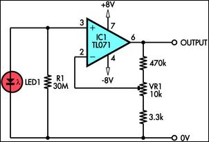
This circuit demonstrates the use of a standard LED as a light sensor. It utilizes the photovoltaic voltage generated across the LED when exposed to light. LEDs are more cost-effective than photodiodes and feature an integrated filter, which is...
Due to their speed, accuracy, effectiveness, and cost-efficiency, infrared (IR) digital thermometers have supplanted traditional mercury thermometers. An ear digital thermometer utilizes a thermopile sensor to measure the infrared heat emitted by the eardrum, which correlates with the temperature...
A modulated current is supplied by the integrated rotational speed sensor KMI 15/x. This current signal needs to be converted into a ground-referenced voltage signal. The KMI 15/x sensor operates by generating a modulated current proportional to the rotational speed of...
A distance sensor would be a beneficial addition to Mindstorms robots; however, ultrasonic sensors tend to be bulky and power-intensive. Simple infrared methods, like those used in radar cars, can detect obstacles but do not provide accurate distance measurements....
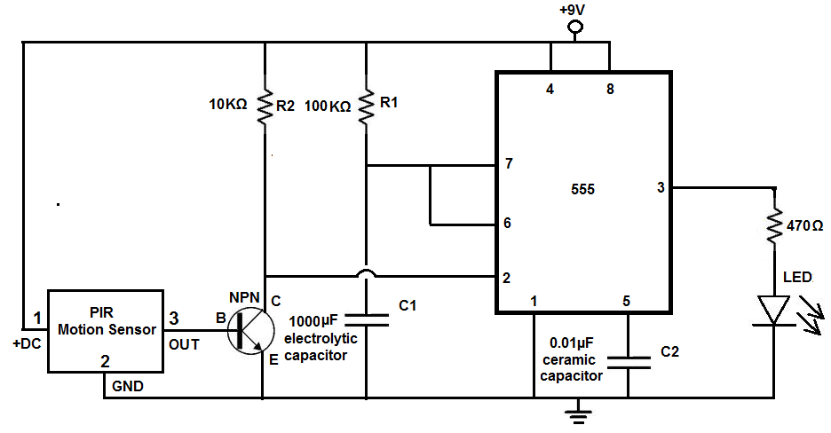
Many individuals install motion detectors in their backyards or homes to automatically turn on lights when movement is detected. Motion sensor lights have gained popularity and are increasingly utilized in various settings. Businesses frequently employ them in bathrooms, where...
Warning: include(partials/cookie-banner.php): Failed to open stream: Permission denied in /var/www/html/nextgr/view-circuit.php on line 713
Warning: include(): Failed opening 'partials/cookie-banner.php' for inclusion (include_path='.:/usr/share/php') in /var/www/html/nextgr/view-circuit.php on line 713