
Zipper Sensor

The circuit design features a series configuration of 45 resistors, each rated at 220 ohms, to achieve a total resistance of 10k ohms. This configuration is critical for creating a variable resistor effect, allowing for fine-tuning of the analog sensor's response based on the position of the zipper slider. The analog zipper sensor is constructed using a plastic zipper, which serves to maintain electrical isolation between the two sides when the zipper is not fully engaged. This isolation is essential to prevent erroneous readings from the sensor when the zipper is not in use.
For the digital zipper sensor, the use of a nickel zipper allows for contact points at the teeth, which can be utilized as switches. Each tooth's capability to transmit different data is a significant advantage, as it enables the detection of various positions along the zipper's length. The conductive thread acts as a bridge between the zipper teeth and the electronic components, ensuring a reliable connection. The integration of soldered conductive beads at both ends of the resistors enhances the overall durability and conductivity of the connections.
The overall design is aimed at creating a dual-function sensor system that can provide both analog and digital outputs, making it versatile for various applications. The analog output can be used for applications requiring continuous variable resistance, while the digital output can be employed in scenarios where discrete position sensing is required. This innovative approach to zipper sensors can significantly enhance user interaction with garments, integrating technology seamlessly into everyday clothing.I used 45 peices of 220 ohm resisters to make 10k ohm variable resister. By banding the wire of the resister I made hook to sew it through. If you want even less volume than normal resister, you can use tiny surface mount resister. To tie with the thread, solder conductive beads at the both end of the resister. I made two different types of input with zipper sensor - analog and digital. My initial thought was to make liner analog potentiometer by using the slider as connecter. Yet during producing, I begin to think any handmade physical device might be not reliable to use as sensor. Conductive thread might create some iragualer resistence. Stiching unit is not always exactlly same so that the value change would not follow exactlly as the movment of the slider.
Thus I planed to make an analog and a digital zipper sensor with in same length so that both can be compared with the motion reading. For the analog I used plastic zipper to secure disconnection between both sides. And for the digital I used nickel zipper because some of the teeth will function as contact point of switches.
My first step was to choose an analog in sensor as resference to new zipper sensor. I chose the most common turning nob type 10k ohm potentiometer for the reference. Since it is 10k ohme variable resister, I design to have 46 pieces of 220 ohm resister in line to have detailed value in proper length of zipper. It ended to be about 24 inch. When the zipper is applied to jackets or shirts, pull down resister is needed next to the signal thread.
Because when both sides of the zipper are totally separated, the signal thread will loose the connection to the ground and give random value. The slider itself has the perfect structure to connect two stich lines sewed in the opposite sides. Though the zipper teeth are made out of plastic, usually sliders are made of painted nickel. So by sanding the inside part of the slider body where it holds the tape, slider can tranfer the electricity from one stich to the opposite side one.
Red marks below are connecting parts between the thread and the slider. The method of digital zipper sensor is multiple switch. The metal zipper - copper, nickel and aluminum zipper - has appropreate structure for liner multiple switch. My initiate thought was that when metal zippers are closed it will have continuety from top to the bottom.
But the fact was not. Each teeth are separated from each other unless the tape is bent more than 120 degree angle in vertical. This means each teeth can transfer different datas. So if I tie the conductive thread to touch the opposite side tooth when the zipper is closed, I can make a single swi
🔗 External reference
Related Circuits
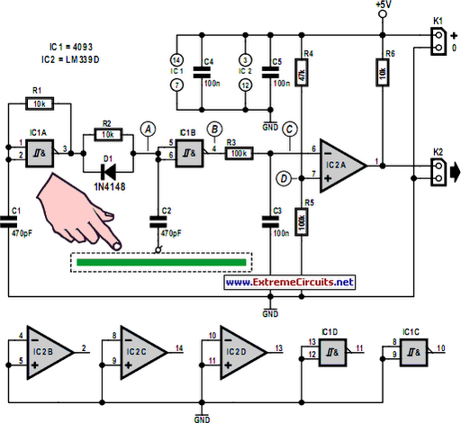
Capacitive touch sensors operate based on the electrical capacitance of the human body. When a finger approaches the sensor, it establishes a capacitance to Earth ranging from 30 to 100 pF. This phenomenon can be utilized for proximity detection...
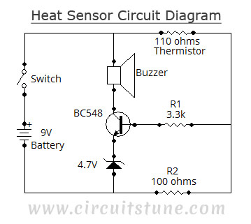
This simple heat sensor circuit can detect heat from various electronic devices such as computers and amplifiers, generating a warning alarm when overheating occurs. It can also sense heat from the environment, but it is primarily designed for use...
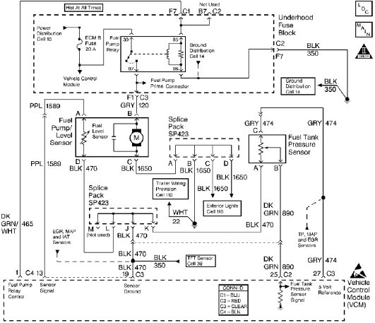
The control module monitors the fuel tank pressure (FTP) sensor signal to detect vacuum decay and excess vacuum during the enhanced evaporative emission (EVAP) diagnostic. The Fuel Tank Pressure Sensor responds to changes in the fuel tank pressure or...
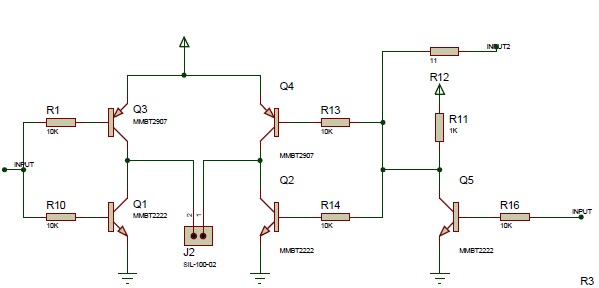
The Proteus files can be found. Recently, four pairs of ultrasound MA40S4 receivers/transmitters from Murata were purchased. They function as a pair of ultrasound microphones and speakers. The objective is to build a simple homemade ultrasound sensor for detecting...
A touch sensor relaxation oscillator is utilized in the hysteresis lab. In this schematic, the variable capacitor is represented by a person's finger and a touch plate made from aluminum foil and packing tape. Code was developed for the...
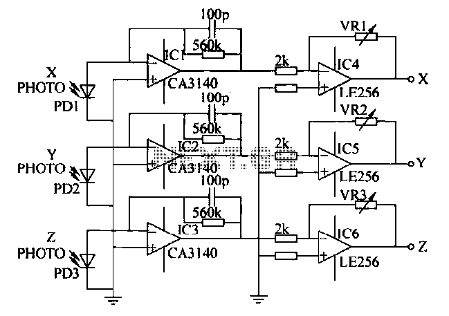
A semiconductor color sensor is designed to identify the color of an object using three photodiodes (PD1, PD2, PD3) and three corresponding color filters (X-PHOTO, Y-PHOTO, Z-PHOTO). Each photodiode is paired with a specific color filter: red (R), green...