
4011 IC For Protection Surge Electronic CIrcuit Diagram
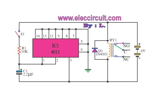
The 4011 IC is a quad 2-input NAND gate, which can be employed in various electronic applications, including surge protection circuits. In this specific application, the circuit utilizes the NAND gates to create a delay mechanism that protects connected appliances from voltage spikes or surges.
The basic operation of the circuit involves the use of the 4011 IC to monitor the input voltage levels. When a surge is detected, the circuit will momentarily disconnect the output to prevent damage to the appliances. The delay feature is crucial, as it allows for transient surges to dissipate before re-engaging the output.
The schematic typically includes the 4011 IC connected to a power supply, input surge detection components (such as diodes or varistors), and output control elements (like relays or transistors) to manage the power to the connected appliances. Resistors and capacitors are also included to set the timing for the delay and filter out noise.
This circuit is particularly beneficial in environments where electrical surges are common, providing an essential layer of protection for sensitive electronic devices. The design should ensure that all components are rated appropriately for the expected voltage and current levels to maintain reliability and safety.This circuit shows about 4011 IC For Protection Surge Electronic CIrcuit Diagram. Features: used to delay other appliances connected to the output .. 🔗 External reference
Related Circuits
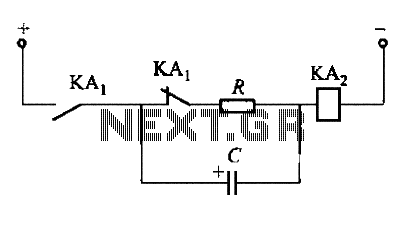
To fulfill the requirements of a control loop, it is often necessary to utilize an electromagnetic relay or a transistor relay to either accelerate or delay an action, thereby forming an acceleration or delay circuit. The circuit depicted in...
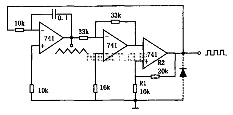
The circuit illustrated generates a variety of low-frequency waveforms, specifically triangle and square waves, simultaneously. It consists of several stages: the first stage is an integrator, followed by a gain stage with an inverter, and a comparator stage that...
In many countries, it is now mandatory or at least recommended to have a rear fog light on a trailer. There is an additional requirement that when the trailer is connected to the vehicle, the rear fog light of...
This page features basic, visible light photo-detector circuits that can be used to detect trains. These methods would normally be used with the photo sensor mounted between the rails. The described photo-detector circuits are designed to detect the presence of...

Often, there is a need for an additional telephone ringer in an adjoining room to be alerted about incoming calls. For instance, if the telephone is situated in the drawing room, an extra ringer may be required in the...
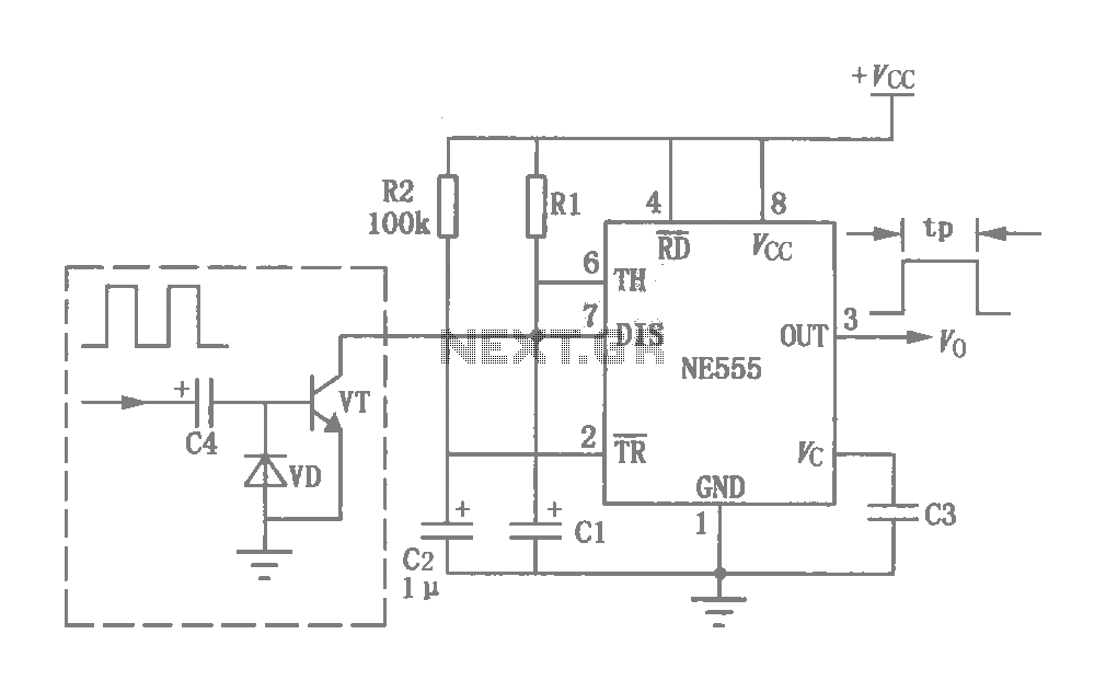
This circuit was originally a type of power-delay control circuit, where the delay time is determined by the timing elements R1 and C1. Additionally, with the inclusion of a "watchdog" circuit, it can be utilized as a monitoring circuit...