
Relay Toggle Switch
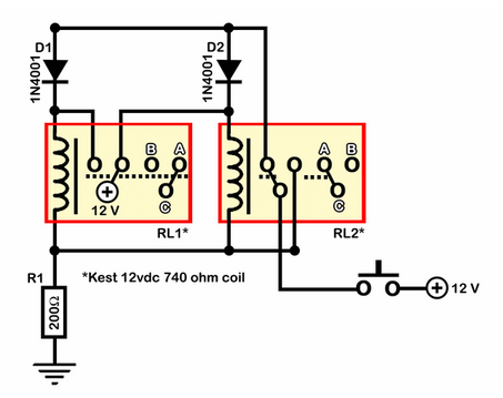
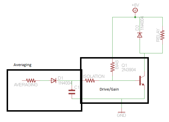
The circuit operates above ground, with one point referenced to positive voltage, which deactivates the relays. RL1 remains off while it applies positive voltage from its armature, thereby latching RL2 in the active state. The application terminals are designated as [A]. When the momentary switch S1 is engaged, voltage is supplied to RL2, latching RL1 in the active state. Releasing S1 turns RL2 off. Subsequently, RL2's armature connects to resistor R1, with terminals switched to [B]. Upon pressing S1 again, the negative side of the relays is referenced to positive, resulting in RL1 turning off due to the absence of current flow. RL2 activates again when S1 is released, reverting the terminals back to [A]. There is a slight delay between the relays' operation, depending on the duration S1 is held. Should different relays be employed, adjustments to the value of R1 may be necessary; for instance, OEG relays (12 VDC, 270-ohm coil) require R1 to be set between 60 to 70 ohms. The primary motivation behind this design is to eliminate the need for toggle switches in an audio control panel. Additionally, the circuit can be operated via a remote transmitted pulse. Relays can be sourced from allelectronics.com.
This relay circuit utilizes a pair of relays configured as a double-pole double-throw (DPDT) switch, allowing for a versatile control mechanism in various applications. The momentary switch S1 serves as the primary control input, providing a simple means to toggle the state of the relays. The design ensures that each relay can be latched independently, facilitating the transition between two distinct states represented by terminals [A] and [B].
The inclusion of resistors, such as R1, plays a significant role in managing the current flow to the relays, thus influencing their response times and overall behavior. The specified resistance values are crucial for ensuring that the relays operate within their rated specifications, particularly when substituting different relay types. The circuit's reliance on a momentary switch allows for temporary activation, making it suitable for applications requiring brief control inputs, such as in audio systems.
Moreover, the potential to control the circuit remotely expands its functionality, enabling integration into more complex systems without the need for physical access to the toggle switch. This feature is particularly advantageous in scenarios where the control panel is not easily accessible.
In summary, this relay circuit is a practical solution for applications requiring a toggle switch functionality without the complexity of integrated circuits. Its straightforward design, adaptability to different relay types, and remote control capability make it a valuable addition to any electronic project.A relay circuit to function as a DPDT toggle which is controlled by a momentary switch. I strive to keep my circuits simple with little or no integration (555`s, transistors, etc). The circuit is shown active or on mode. Half of RL1 and RL2 manipulate the switching and the other is connected to an application. Relays are 200 ohms above ground and at one point are referenced to positive that turns them off. RL1 (which is off) applies plus voltage from its armature and latches RL2 on . The application terminals are set to [A]. The condition changes when S1 is activated, voltage is applied to RL2 latching RL1 on releasing S1 turns RL2 off . RL2`s armature is then directed to R1. Terminals are set to [B]. When S1 is pressed again, the relays negative side are referenced to positive, RL1 turns off (there`s no current flow).
RL2 turns on when S1 is released, terminals are set to [A]. There is slight lag between relays depending on how long S1 is held. If different relays are used, adjustment of R1`s value may be required. For example, OEG relays (12vdc, 270 ohm coil) need R1 at 60 70 ohms. The prime motivation for this design was to avoid using toggle switches for my audio control panel. Another plus, it can be controlled from a remote transmitted pulse. Relays are available at allelectronics. com 🔗 External reference
Related Circuits
The voltage regulator integrated into the Arduino Uno is a linear-type regulator, which exhibits poor efficiency. When operating the ATmega238 at 5V with a 9V battery, nearly half of the battery's energy is wasted as heat by the regulator....
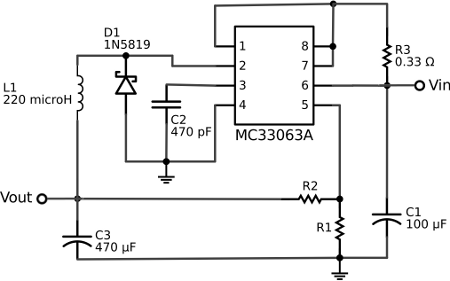
This 5-volt Switch Mode Power Supply circuit utilizes an integrated circuit (IC) from National Semiconductor, which specializes in the production and design of ICs for switch-mode power supply applications. The 5-volt Switch Mode Power Supply (SMPS) circuit is designed to...
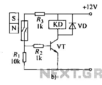
The automatic weapon features a magnetic switch circuit that is simple, reliable, has a low failure rate, and offers good versatility. It can be used to output performance or convert mechanical displacement. The circuit diagram utilizes a Hall switch...
A circuit that activates a relay upon detecting audio pulses from one channel of an MP3 player. The intention is to synchronize recorded audio pulses with music to control a motor for mouth movement. For a stereo player, music...
This simple diode modulator delivers excellent results when used for high percentage modulation at low signal levels. Constants are shown for a carrier frequency of about 10 MHz, but with a suitable tank, the circuit will yield good results...
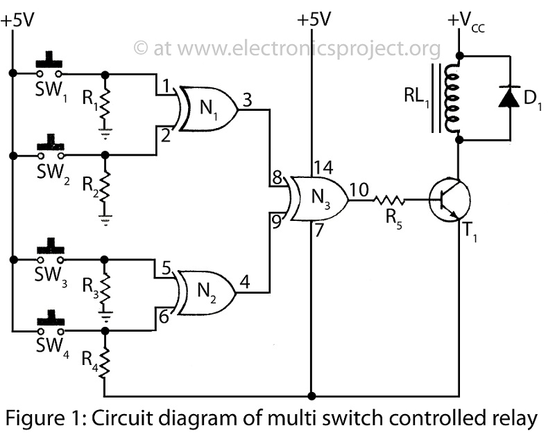
A Multi Switch Controlled Relay circuit is utilized to manage home appliances, featuring a circuit diagram that outlines the application of a multi switch-controlled relay using a single integrated circuit (IC) for various control functions. The Multi Switch Controlled Relay...
Warning: include(partials/cookie-banner.php): Failed to open stream: Permission denied in /var/www/html/nextgr/view-circuit.php on line 713
Warning: include(): Failed opening 'partials/cookie-banner.php' for inclusion (include_path='.:/usr/share/php') in /var/www/html/nextgr/view-circuit.php on line 713