
Multi Switch Controlled Relay
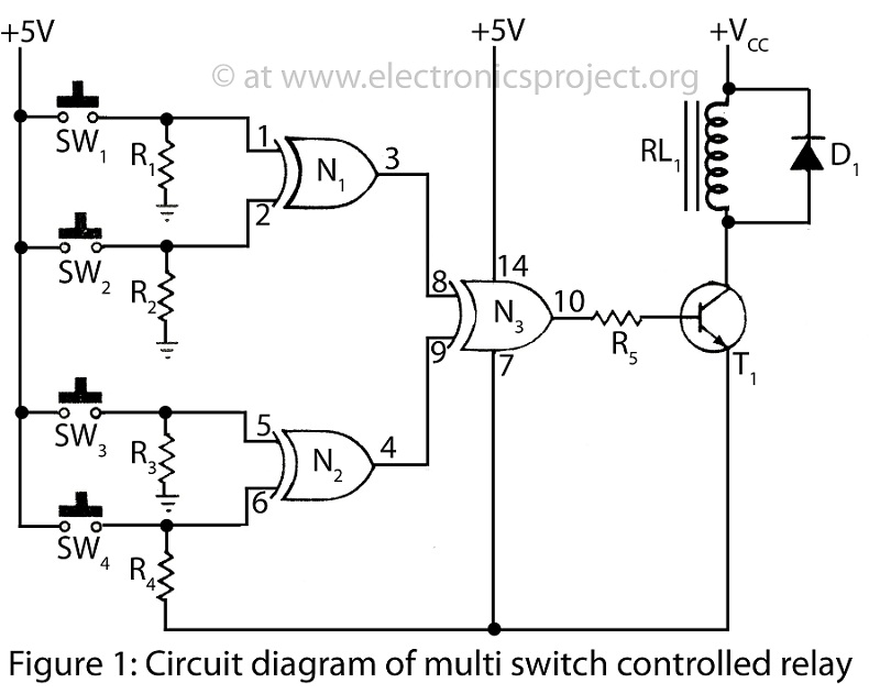
The Multi Switch Controlled Relay circuit operates by allowing multiple switches to control a single relay, thus enabling the activation or deactivation of home appliances from different locations. The circuit typically includes a relay, which acts as an electromechanical switch, and one or more control switches that can be positioned strategically throughout the home.
The core component of this circuit is an integrated circuit (IC) designed for control purposes. This IC can handle multiple input signals from the switches and use them to drive the relay. When a switch is activated, the IC processes the signal and energizes the relay coil, closing the relay contacts and allowing current to flow to the connected appliance.
The schematic diagram for this circuit will typically depict the IC, the relay, and the switches. The IC may include additional components such as resistors, capacitors, and diodes for signal conditioning and protection. For example, a diode may be placed in parallel with the relay coil to prevent back EMF from damaging the IC when the relay is turned off.
In practical applications, this circuit can be used to control lights, fans, or any other electrical appliance, providing convenience and flexibility for users. The ability to control an appliance from multiple locations enhances user experience and can improve energy efficiency.
Overall, the Multi Switch Controlled Relay circuit represents a versatile solution for home automation, leveraging a simple yet effective design to enhance control over household devices.Multi Switch Controlled Relay circuit is used to control home appliance circuit diagram with description of multi switch controlled relay utilization 1 IC various control IC. 🔗 External reference
Related Circuits
The project originated from a request by Tony Bowler, a member of the Long Eaton Club, who sought assistance in converting a "Golden Oldie" model to electric free-flight. He selected Vic Smeed's "Debutante" to be powered by seven AE...
This circuit requires a control current that is 100 times smaller than that required by standard optically isolated solid-state relays. It is particularly suitable for battery-powered systems. By utilizing a combination of a high-current TRIAC and a very sensitive...
Individuals seeking a distinctive gift for Christmas and New Year may find this project appealing. Certification of this project will undoubtedly create a preference for it. The project in question appears to be a creative endeavor aimed at providing a...
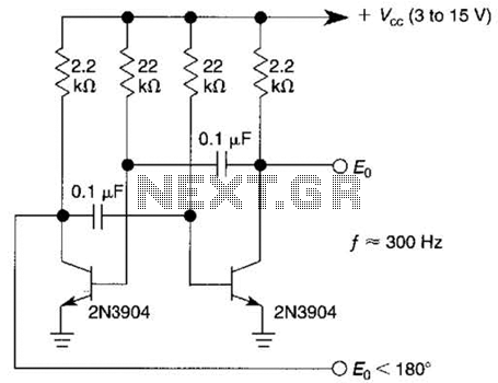
This free-running square-wave oscillator utilizes two NPN transistors. The output frequency is approximately 300 Hz with the specified component values. The circuit operates as a basic oscillator, generating a square wave output through the interaction of two NPN transistors. The...

The electronic switch selection allows for multiple temperature control and monitoring points. It utilizes OP27 in conjunction with multiple S-type thermocouple circuits. The DG801/802 ultra-low on-resistance electronic switch has a maximum on-resistance of 0.40 ohms and operates under single-supply...
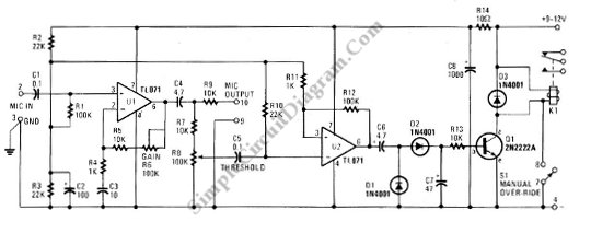
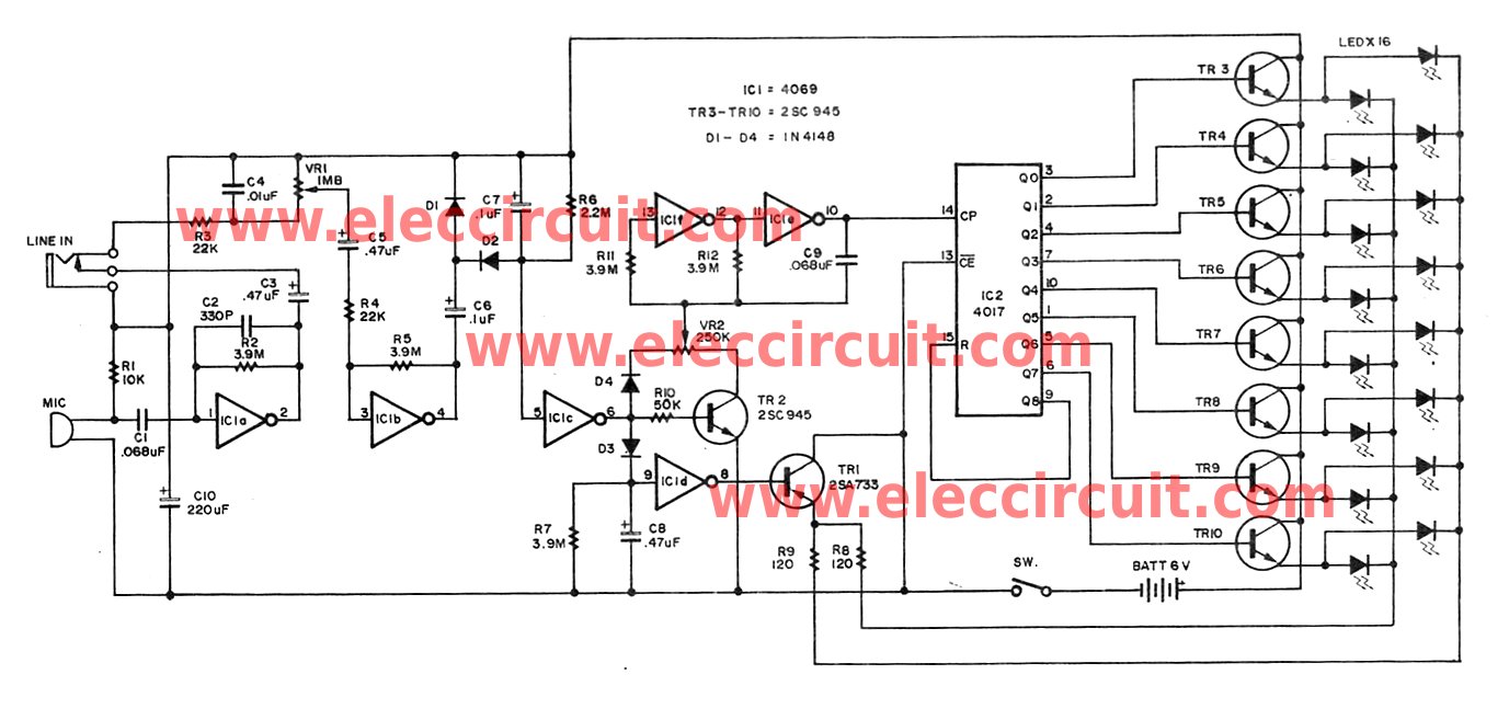
This schematic diagram below shows a circuit of a VOX Box (voice-operated switch). This circuit consists of a Schmitt trigger, a relay driver, and a microphone. The VOX Box circuit operates as a voice-activated switch, utilizing a microphone to detect...