
rem bell circuit
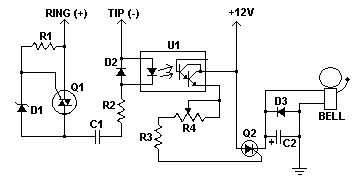
The remote telephone bell ringer circuit is designed to enhance the auditory signaling capability of standard telephones. The circuit operates by detecting the ringing signal from the telephone line, which is typically a low-voltage AC signal. Upon detection, the circuit activates a TRIAC or SCR (Q1 or Q2) to control the power delivered to an external bell.
The use of a TRIAC or SCR allows for efficient switching of higher voltage and current levels required by large bells. The choice of these components must consider their voltage ratings and current capacities to ensure reliable operation. Q2, which directly controls the bell, must be rated to handle the maximum current that the bell will draw during operation.
The circuit includes an opto-isolator, which serves a dual purpose. First, it provides electrical isolation between the telephone line and the power supply, protecting sensitive components from voltage spikes or transients that may occur on the phone line. Second, it minimizes the risk of ground loops, which can introduce noise and interference into the circuit, potentially affecting performance.
Adjustments to accommodate various supply voltages can be made by modifying resistor values or using different power supply configurations, ensuring the circuit remains versatile for different applications. It is also crucial to adhere to local regulations concerning the connection of homemade devices to telephone lines, as non-compliance can result in penalties or safety hazards.
Overall, this remote telephone bell ringer circuit offers a practical solution for enhancing the ringing capabilities of telephones in environments where traditional ringers are insufficient.This remote telephone bell ringer allows you to use a large (and loud) external bell in place or in addition to the built in (and rather wussy) ringer in most modern telephones. This is ideal for large outdoor areas, noisy shops or those hard of hearing. Most any large bell can be used as the circuit can be easily adjusted for various supply volta ges. Virtually any TRIAC and SCR will work for Q1 and Q2 as long as the voltage rating is high enough. Q2 needs enough current capacity to handle the full load of the bell. Make sure to check with local authorities before you connect a homemade device to your phone lines. Some areas mandate that only approved devices can be connected to the loop. This circuit provides an opto-isolator to prevent cosstalk between the phone line and power supply as well as to avoid ground loops. 🔗 External reference
Related Circuits
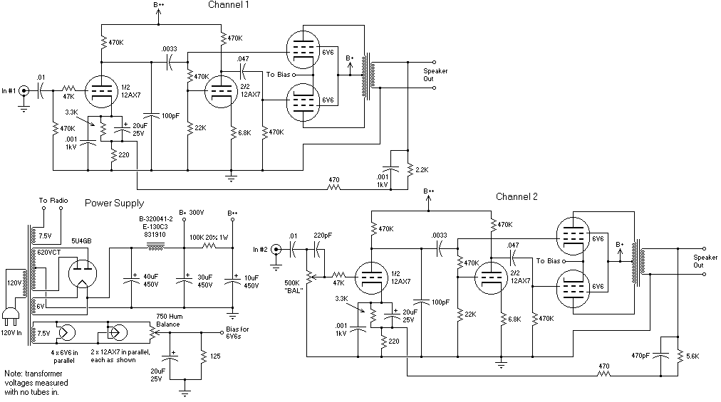
The recommendation regarding the existing phono connector is to maintain its current configuration without making significant alterations. The procedure involves replacing the electrolytic and paper capacitors, adding a three-wire line cord, and utilizing the radio in its original state....
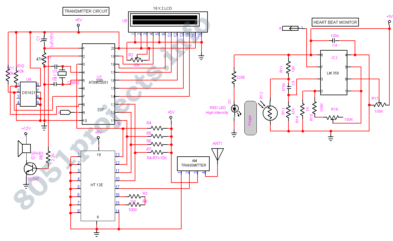
In spite of the improvement of communication link and despite all progress in advanced communication technologies, there are still very few functioning commercial wireless monitoring systems, which are most off-line, and there are still a number of issues to...
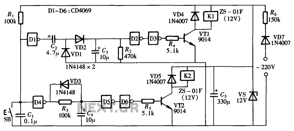
A one-button control switch is designed to control two relays, each of which can switch the load power on and off as needed. The circuit primarily consists of a hex inverter CD4049 and two self-locking DC relays. The circuit utilizes...

The simple pulse width modulation circuit is illustrated in the figure. It utilizes an operational amplifier to create a multivibrator, resulting in a symmetrical oscillation output signal with a duty cycle of 50%. By adjusting the external threshold voltage,...
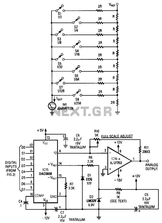
Figure A illustrates an R/2R resistor ladder. Each closed switch increases the current flow. A basic channel A/D converter is depicted in Figure B. The voltage reference (D2) is shared across all channels, although the value of the dropping...
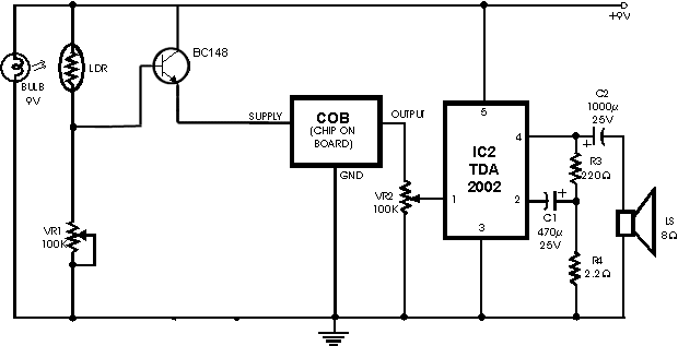
The circuit operates on the principle of detecting smoke produced during a fire, which passes between a light bulb and a light-dependent resistor (LDR). As smoke obscures the light, the amount of light reaching the LDR decreases, resulting in...