
Digital To Analog Converter Circuit
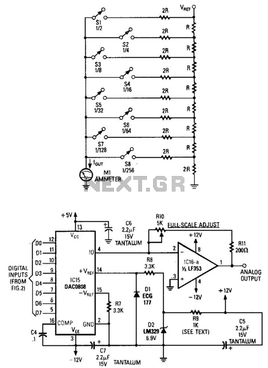
The R/2R resistor ladder configuration is a popular method for digital-to-analog conversion. It consists of a series of resistors arranged in a ladder-like structure, where each switch corresponds to a binary digit (bit). When a switch is closed, it effectively adds or subtracts a specific voltage level to the output, depending on its position in the ladder. The precision of this conversion relies on the matching of resistor values and the stability of the reference voltage.
In the A/D converter illustrated in Figure B, the DAC0808 chip (IC15) is utilized for its ability to convert digital signals into analog voltages. The common voltage reference (D2) ensures that all channels operate with a consistent baseline, which is crucial for maintaining accuracy across multiple DACs. The dropping resistor (R9) plays a vital role in determining the output current, which is affected by the number of DACs in the system. Adjusting R9 allows for proper scaling of the output, ensuring that the system can accommodate varying loads or configurations.
The operational amplifier (IC16A) is employed to interface the output current from the D/A converter. Its primary function is to convert the current output into a usable analog voltage. This is achieved through feedback and gain settings in the op-amp configuration, which can be tailored to meet specific application requirements. The op-amp also provides buffering, which isolates the DAC output from the subsequent stages of the circuit, ensuring signal integrity and preventing loading effects.
Overall, this configuration of R/2R ladder, DAC0808, and operational amplifier creates a versatile and efficient system for converting digital signals into precise analog voltages, suitable for a wide range of electronic applications. Figure A is an R/2R resistor ladder. Each switch that is closed increases the amount of current at . A simple channel A/D converter is shown in Fig. B. The voltage reference (D2) is common to all channels, but-the value of the dropping resistor (R9) varies as the number of DACs installed in the system. IC15 is a DAC0808 A/D converter chip. ICI6A is an op amp to interface the output current from the D/A convert to an analog voltage output. 🔗 External reference
Related Circuits
This article presents a driver circuit for a 12V, 5W fluorescent lamp. The circuit utilizes a standard 220V to 10V step-down transformer operated in reverse to achieve a 12V output. The driver circuit for a 12V, 5W fluorescent lamp is...
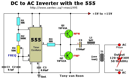
This simple 12V DC to 220V AC inverter circuit generates an AC output at line frequency and voltage. The 555 timer is configured as a low-frequency oscillator, adjustable over the frequency range of 50 to 60 Hz via the...
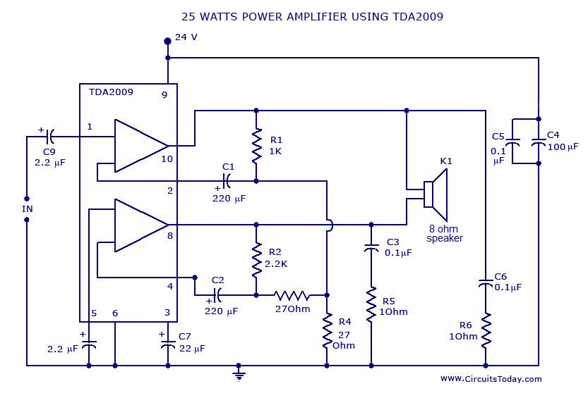
Power amplifier circuit diagram with schematics. This simple audio power amplifier circuit is designed for 25 watts output power using TDA 2009 IC, which has two channels (stereo), 12.5 W for each channel. The described power amplifier circuit utilizes the...
The single-junction transistor is commonly utilized in sawtooth and pulse generators, and it can also be configured to create a basic sine wave generation circuit. As an oscillator circuit composed of discrete components, it requires a minimal number of...
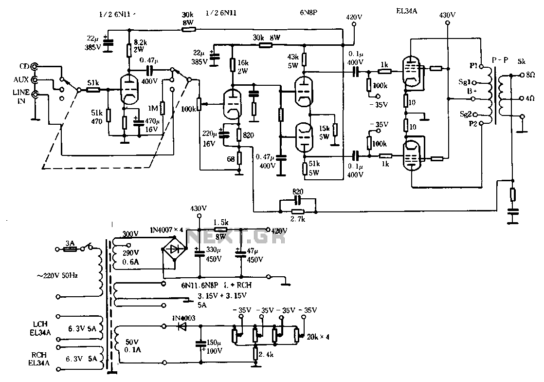
The Ml00 circuit is a typical tube circuit, functioning as a preamplifier. Its input stage utilizes a common cathode amplifier, followed by an inverter stage, culminating in a power amplifier that has been enhanced from a standard connection. This...
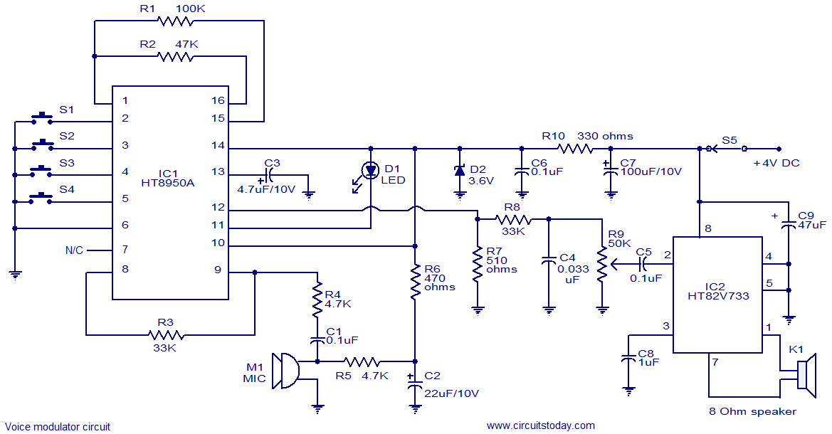
This is a versatile voice modulator circuit utilizing the HT8950A IC from Holtek Semiconductors. The IC can generate seven upward or downward frequency steps based on the input voice at a rate of 8 Hz. Additionally, it features two...