
remote control
The circuit operates by utilizing a keypad interface that allows users to input commands through individual buttons. Each button press activates a corresponding binary code, which is then processed by IC1. The IC encodes the button press into a series of pulses that represent the binary values. This encoding employs the PPM technique, where the timing of the gaps between the pulses carries the information. The longer the gap, the more likely it indicates a binary zero, while shorter gaps correspond to binary ones.
The IR LEDs, connected via diodes D1 and D2, serve as the transmission medium for the encoded signals. These diodes ensure that the signals are directed appropriately and help in modulating the light output to transmit the binary information effectively to a receiving unit.
The inclusion of the SL490 with its automatic standby feature enhances the circuit's efficiency. When the keypad remains idle for a predetermined duration, the SL490 reduces its power consumption by entering a low-power standby mode, drawing only 6 µA. This feature is essential for battery-operated devices, as it prolongs battery life by minimizing energy consumption during periods of inactivity.
Overall, this circuit design exemplifies an efficient method for encoding and transmitting data wirelessly using infrared signals, leveraging pulse position modulation for effective communication while maintaining low power consumption during standby periods.Every key pad button generates 5 bit binary code and IC1 sends this code to the IR leds through D1 and D2 diodes. Code is shaped from 6 pulses with 5 gaps. Pulse position modulation PPM technique is used for transferring data. Data information occurs at gaps. For logic 0, long gap, for logic 1 short gap is generated. SL490 includes an auto sta nd-by circuitry. When the buttons are not used for a while, IC will swich to stand-by mode and stand by current will be 6uA. 🔗 External reference
Related Circuits
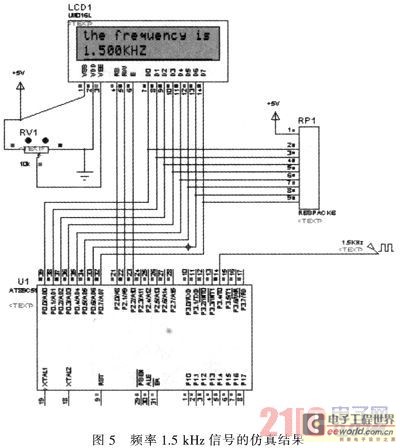
The primary function of the frequency counter is to measure the frequency and cycle of a signal. Its applications span a wide range, extending beyond simple instrument measurements to areas such as education, scientific research, high-precision instrument measurement, and...

Remote Control Mains Switch The remote control mains switch is a device designed to control the power supply to electrical appliances from a distance, typically utilizing a wireless remote control. This switch can be integrated into various applications where remote...

The receiver circuit depicted in the figure requires the insertion of a plug into the radio headphone jack. When the radio receiver detects a signal from the transmitter, an audio signal is output from the jack. This signal is...

The FIG potentiometer RP2 has a sliding contact that is directly connected to the antenna. The system operates such that only when potentiometers RP1 and RP2 are positioned identically, do the non-conductive transistors and rectifier bridge remain off, resulting...

This circuit diagram represents a radio-controlled system, commonly used in toy car applications for children. The circuit consists of two main parts: the transmitter and the receiver. The transmitter generates radio signals using an oscillator circuit formed by transistor...

The FAN7710 Ballast Control IC is designed for use with compact fluorescent lamps (CFLs). This IC is developed using Fairchild's unique high-voltage process and system-in-package (SiP) technology. The FAN7710 is a highly integrated ballast control solution that provides efficient operation...