
Radio remote control circuit

The receiver circuit operates by receiving an audio signal from a transmitter, which is input through a radio headphone jack (XP). The process begins with the detection of the transmitted audio signal, which is then sent to the rectification stage. Diodes VD1 and VD2 serve as rectifiers, converting the alternating current (AC) audio signal into a pulsating DC signal. This pulsating signal is smoothed out by capacitor C2, which acts as a filter, providing a steady DC output that is suitable for further processing.
The output from the filter is connected to the base terminals of transistors VT1 and VT2. These transistors are arranged in a composite configuration, allowing them to amplify the DC signal effectively. When the transistors are turned on, they complete the circuit for relay KD, causing it to activate. The relay is a crucial component in this circuit, as it allows for control over a larger load circuit without the need for direct electrical connection to the control circuit.
Relay KD features both normally open (NO) and normally closed (NC) contacts. The NO contacts close when the relay is energized, allowing current to flow through the connected load circuit. Conversely, the NC contacts open, interrupting the current flow. This dual functionality enables the circuit to be used for various applications, including remote control of lights, fans, or other electronic devices. The design of this receiver circuit provides a simple yet effective solution for wireless control, making it suitable for a range of practical applications in home automation and remote device management.The receiver circuit shown in FIG. Insert the plug XP radio headphone jack xs, when the radio receiver to the hair after the transmitter signal, the audio signal output from xs by VD1, VD2, c2 rectifier filter, the resulting DC signal is applied by the VT1, VT2 constituting the composite tube base, turning it on, so the relay KD pull. KD pull, can use its normally open and normally closed contacts connected to any load circuit, realize the wireless remote control to turn on or off.
Related Circuits
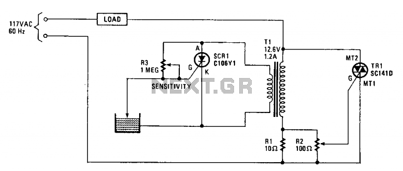
The operation of the circuit is based on the difference in the primary impedance of a transformer when its secondary is loaded compared to when it is open-circuit. The impedance of the primary of T1 and resistor R1 are...
When using microcontrollers in designs, a common challenge is displaying user-required data. Solutions such as multiple LEDs, 7-segment displays, or LCD modules can be employed, but displaying a large amount of information simultaneously can pose difficulties. Large LCD modules...
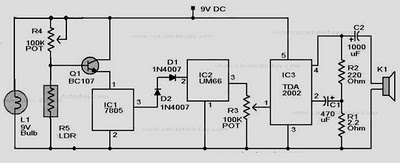
When there is no smoke, the light from the bulb directly illuminates the Light Dependent Resistor (LDR). In this condition, the resistance of the LDR is low, resulting in a voltage drop of less than 6V across it. Consequently,...
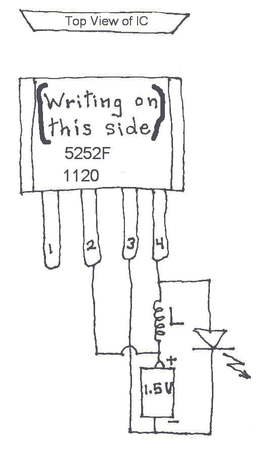
Many Joule Thief circuits traditionally rely on a bulky toroidal inductor that requires careful winding with copper wire. However, there are now compact 4-legged integrated circuits (ICs) available that can perform the same function using only a simple inductor,...
This circuit utilizes the TA7222AP to amplify audio signals. The cost is only $0.99, and it can provide 5.8 watts with muting control. The power supply can be in the range of 8-12 VDC, making it suitable for applications...
Most peripherals that interface with a PC utilize a USB port. The computer's power supply circuit, specifically the switched-mode power supply (SMPS), is designed to provide constant power to all internal components. However, when external peripherals that require a...