
remote_control circuit
The described circuit utilizes a photocell as the primary sensing element, which is sensitive to light levels. The photocell's resistance decreases with increasing light intensity, allowing for the creation of a voltage divider when combined with resistive components. This voltage divider's output voltage is directly proportional to the light intensity, which can be monitored and amplified using an operational amplifier or a transistor-based circuit.
To implement this design, the circuit can include a power supply, typically a DC voltage source, connected to the photocell and resistive components. The output from the voltage divider can be fed into a comparator circuit to determine when the voltage exceeds a certain threshold, indicating that the light level is sufficient to trigger the desired action. This comparator can be configured with hysteresis to prevent rapid switching due to minor fluctuations in light levels.
The activation of the relay or SCR can be accomplished by connecting the output of the comparator to the gate of the SCR or the coil of the relay. This allows the circuit to control higher current loads, such as lights or motors, which require more power than the photocell can handle directly.
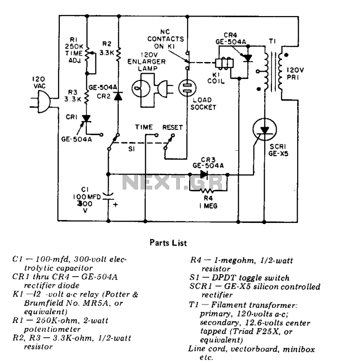
The placement of the photocell in a matte black tube is crucial to ensure that it only responds to the intended light source, thereby preventing false triggers from ambient light. The potentiometer R2 allows for fine-tuning of the sensitivity of the photocell, enabling the user to set the threshold level at which the circuit will activate based on their specific requirements.
Overall, this circuit design offers versatility in its applications, allowing users to creatively implement it in various scenarios, from simple lighting controls to more complex automation systems.At this circuit you can give a variety of utilities, from an alarm, to open a door, turn on a light in the garden or courtyard, and so on. Your imagination has the last word. HOW IT WORKS: The operating principle is based on the properties of a photoelectric PHOTOCELL or light, the substances with which this is constructed, its resistance varies w
ith the degree of light it receives. When this component is placed in series with other components resistive, and then connect to the poles of a power supply, you get a voltage divider, which is dependent on the light. When these variations amplified voltage properly, we can activate a relay (relay, relay, circuit breaker), an SCR (silicon controlled rectifier), a triac, and so on.
and I manage teams with higher amperage. The PHOTOCELL (light) should be placed inside a tube in black matte color so they do not receive the light of day or other than that which will operate the circuit. The potentiometer R2 is responsible for adjusting the amount of voltage that should receive the PHOTOCELL and thus with that degree of light should turn on the circuit.
🔗 External reference
Related Circuits
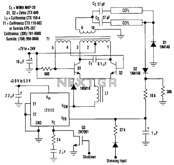
This circuit is a 92%-efficient power supply for cold-cathode fluorescent lamps (CCFLs), which are used to backlight LCDs in portable equipment. The efficiency depends heavily on the component types, particularly C1, Q1, Q2, L1, and T1, whose manufacturers are...
This Intercom is powered by two 9-volt batteries and uses only current when the Intercom is used. Both units are connected via a two-wire little cable or simply two wires (dotted lines). The loudspeakers act both as loudspeakers and...
This is a circuit design for a temperature relay that can be used to signal a fire or monitor temperature set points. The adjustment of P1 is necessary to ensure that the base voltage of T1 is 0.5V lower...
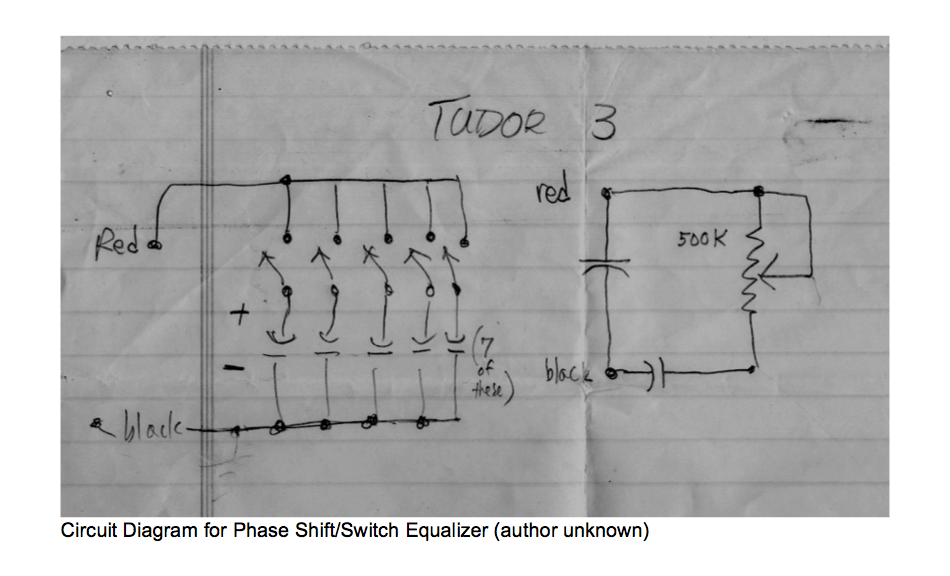
This circuit allows for the adjustment of resistance using a potentiometer and the adjustment of capacitance by opening or closing switches. By manipulating the configuration of these switches, various combinations can be achieved to obtain different effective capacitance values....
The count switching circuit consists of an electronic switch and a pulse delay circuit for control. The count switching circuit is designed to manage the switching of signals in a controlled manner. The electronic switch serves as the primary component...
This precision solid-state time delay circuit features both delayed off and delayed on switch functions, which can be interchanged by simply swapping the relay contacts. The described time delay circuit is designed to provide precise control over the timing of...
Warning: include(partials/cookie-banner.php): Failed to open stream: Permission denied in /var/www/html/nextgr/view-circuit.php on line 713
Warning: include(): Failed opening 'partials/cookie-banner.php' for inclusion (include_path='.:/usr/share/php') in /var/www/html/nextgr/view-circuit.php on line 713