
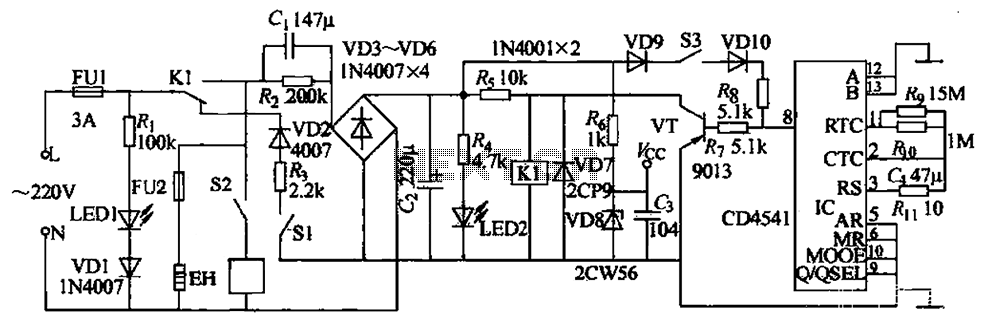
Optionally extended charging pulse count switch circuit diagram
The count switching circuit is designed to manage the switching of signals in a controlled manner. The electronic switch serves as the primary component for toggling the circuit states, allowing for the connection or disconnection of various circuit paths based on the control signals received. This switch can be implemented using a variety of technologies, including transistors, MOSFETs, or relays, depending on the required specifications such as load current, voltage, and switching speed.
The pulse delay circuit is crucial for ensuring that the switching occurs at the appropriate time. It introduces a predefined delay in the control signal, allowing for synchronization between different components in the system. This delay can be achieved using capacitors and resistors in an RC timing configuration or through more complex digital delay circuits, depending on the precision and flexibility needed in the application.
In operation, when a control signal is generated, it first passes through the pulse delay circuit, which modifies the timing of the signal before it reaches the electronic switch. This ensures that the switch only activates after the specified delay, preventing premature switching that could lead to circuit malfunction or damage. The overall design of the count switching circuit allows for efficient control of multiple outputs or stages in electronic systems, making it suitable for applications such as digital counters, timers, and automated control systems. As shown, the count switching circuit comprises an electronic switch and a pulse delay circuit control.
Related Circuits
This sound level meter circuit can be used to control the intensity of a sound recording or in a disco. It has 5 measurement domains between 70 and 120 dB. The sound level meter circuit is designed to measure sound...
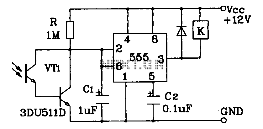
Darlington phototransistor type light-sensitive switch control circuit application. The Darlington type phototransistor serves as a sensitive element, capable of detecting low light levels for the detection of reflected light signals. The Darlington phototransistor circuit utilizes a pair of transistors configured...
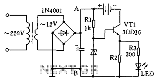
A practical single-tube constant current charger is illustrated, utilizing a transistor (VT1) that plays a crucial role in maintaining a constant current. The current value is determined by the voltage regulator and resistor R2. The general output voltage is...
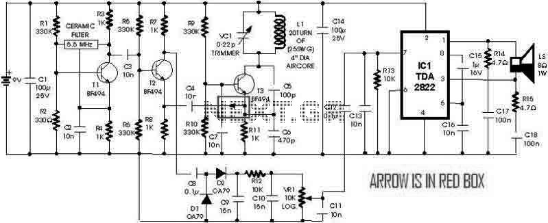
This is a simple metal detector utilizing a TDA2822 and several NPN transistors. An arrow indicates the signal flow direction from the Emitter of transistor T3 to the 10nF capacitor C4, which is opposite to the typical left-to-right flow...
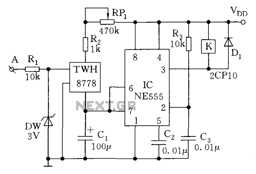
The circuit element appears to be problematic, particularly with the Shu component. After a prolonged period following the activation of the start button, there are indications of unexpected behavior, such as the turtles producing sperm-like substances. The Pi Wen...
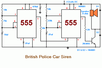
This circuit displays a sound generator that simulates the siren of a British police car. The circuit is constructed using two timer IC 555. The sound generator circuit designed to simulate a British police car siren utilizes two 555 timer...