
Temperature Relay Circuit

The temperature relay circuit typically consists of a temperature sensor, a transistor, and a relay. The temperature sensor can be a thermistor or an integrated circuit temperature sensor, which provides an output voltage that varies with temperature. This output is fed into the base of the transistor (T1), which acts as a switch to control the relay.
In this design, the potentiometer (P1) is used to fine-tune the base voltage of the transistor. By adjusting P1, the voltage at the base of T1 can be set to be 0.5V less than the emitter voltage, ensuring that the transistor operates correctly within its active region. This precise adjustment is crucial for accurate temperature detection and relay operation.
When the temperature exceeds the predetermined threshold, the voltage from the temperature sensor will rise, causing the base-emitter junction of T1 to become forward-biased. This will allow current to flow through the collector-emitter path of the transistor, energizing the relay coil. The relay can then activate an alarm system or a fire suppression mechanism.
The circuit may also include additional components such as resistors to limit current, capacitors for stability, and diodes for flyback protection across the relay coil to prevent voltage spikes when the relay is de-energized. Proper layout and component selection are essential to ensure reliable operation and to minimize false triggering due to noise or transient signals.This is a design circuit for temperature relay that can be used to signal a fire or set point for temperature monitoring function. You need to adjust P1 so that T1?s base voltage is 0.5V smaller than the emitter voltage at a temperature a little bit..
🔗 External reference
Related Circuits
The individual expressed frustration while attempting to connect a circuit to a 15V supply, bypassing resistor R3 with a clip-on soldering heat sink. They noted that 555 timers emit a distinct odor when damaged. They have limited components remaining...

A zero-crossing detector converts an input sine wave (Vin) into a square wave, which, when high, charges an op-amp integrator. A reference-input square wave subsequently discharges the integrator. The output voltage of the integrator at the end of this...
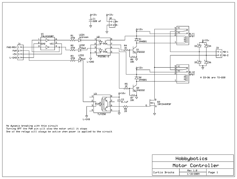
Develop a cost-effective high-current circuit that utilizes PWM. The design includes flyback diodes to protect the MOSFET from the back EMF generated by the motor when the power is switched on and off via the PWM signal. This configuration...

This circuit is a simple mixer circuit that can mix two signal channels into one output channel. It utilizes a codec circuit to convert stereo audio into mono audio. The circuit can also increase the number of channels by...
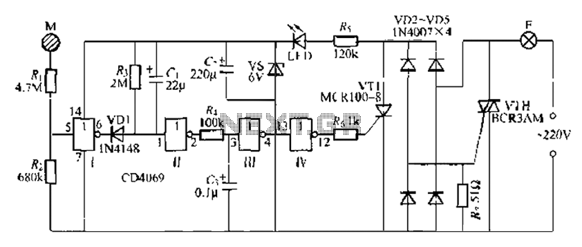
The CD4069 is a digital integrated circuit that utilizes boron to delay the activation of a light touch. It employs a j-wire connection force method and can directly replace a standard light switch without requiring changes to the existing...
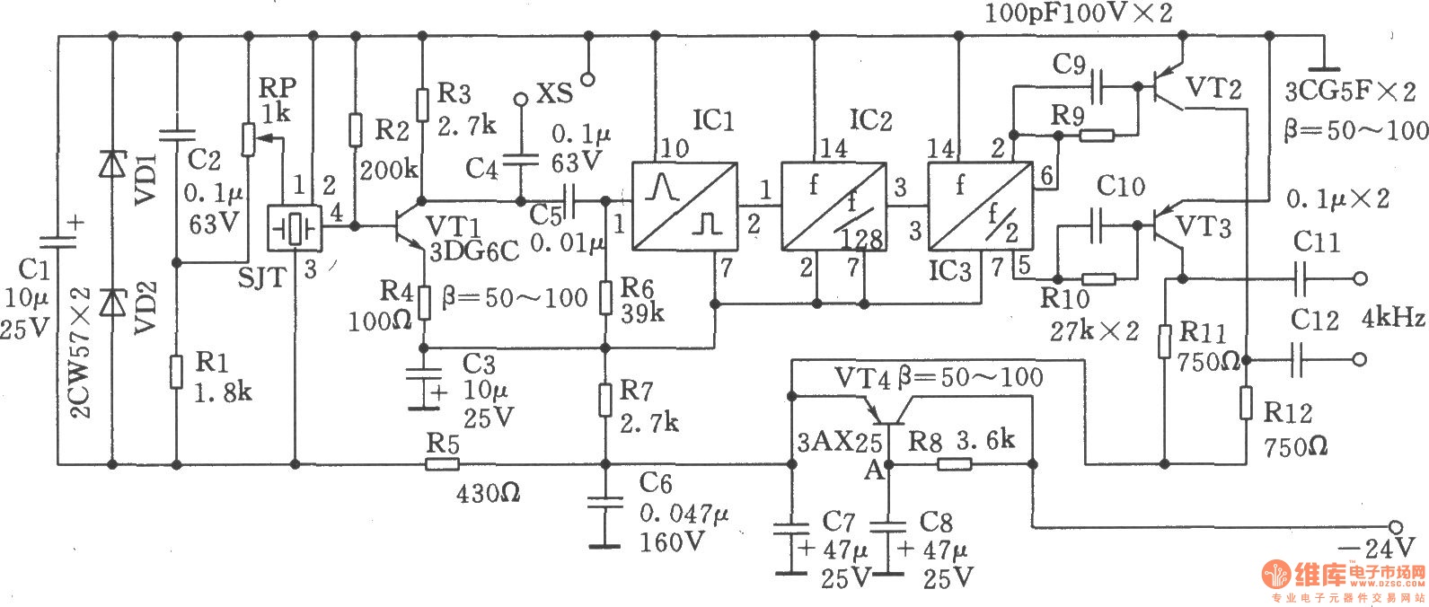
The circuit SJT is a 1024 kHz warming crystal oscillator. The circuit is illustrated in the accompanying chart. Due to the low output signal level, a transistor (VT1) is employed as a buffer amplifier. The base bias resistor (R2)...