REMOTE CONTROL CIRCUITS
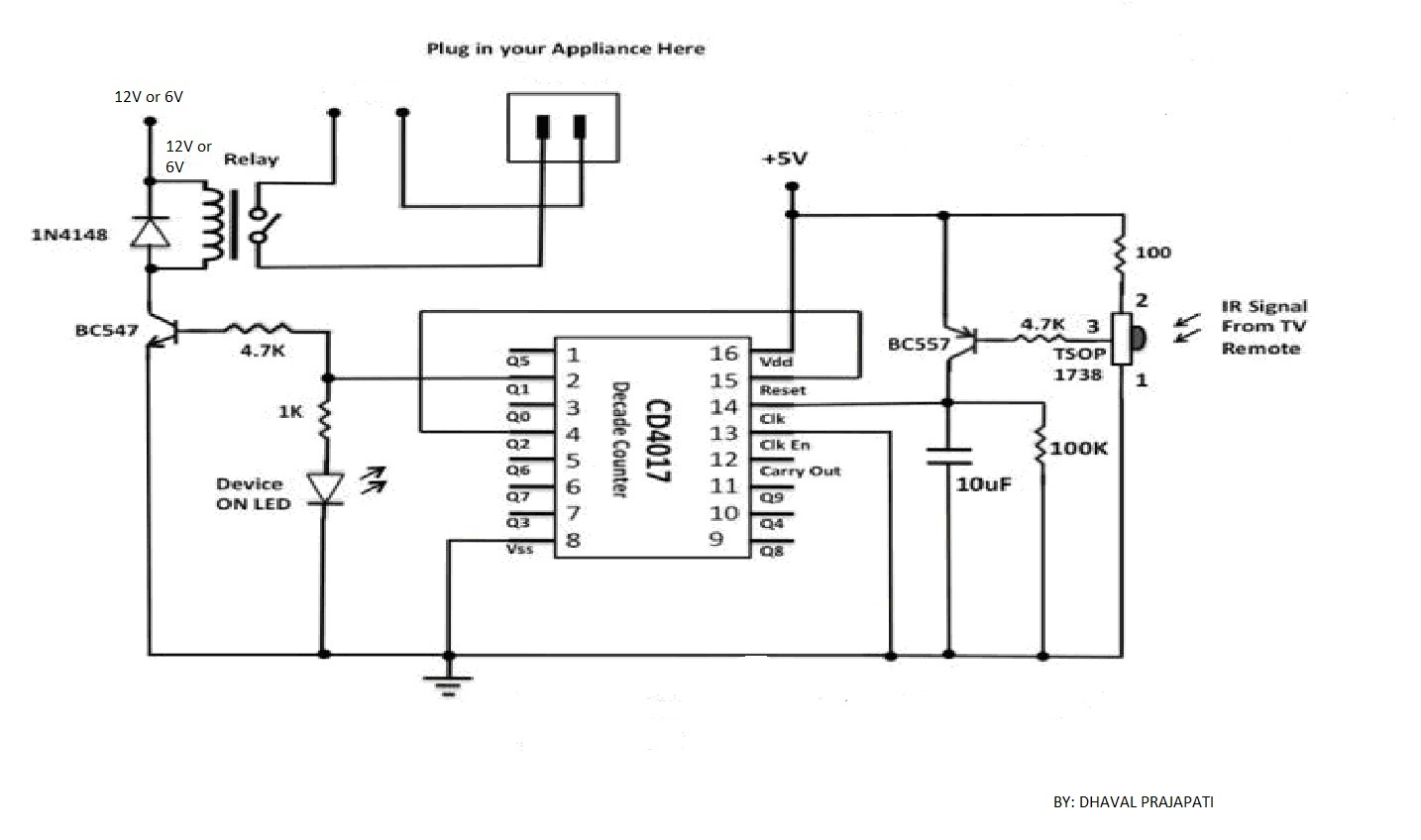
The circuit utilizes a 4-bit encoder to generate data, which is then modulated using an RF modulator for transmission. On the receiving end, the signal is demodulated, and a decoder retrieves the 4-bit data. The pin configuration for the HT12E and HT12D is provided, featuring 8-bit address pins that allow for the generation of 256 unique addresses. Data transmission occurs only when the addresses match on both sides. Address generation can be accomplished using DIP switches, which can be connected to the address pins instead of grounding them directly. The last four pins in the receiver circuit serve as data pins, defaulting to a digital high (5V) output. When the corresponding pin on the transmitter side is grounded, the same pin on the receiver side outputs a digital low (0V). This circuit can be applied to create an RC car or an RC home appliance controller. The system employs IR LEDs to emit rays that reflect off surfaces; if the surface is white, the rays are captured by an IR sensor, triggering the circuit. This results in a 5V signal being applied to an NPN transistor, activating it and allowing a 12V drop across the motor, which starts the motor. The design can be adapted for a white line follower by replacing the NPN transistor with a PNP transistor.
The circuit design incorporates a 4-bit encoder, such as the 74HC148, which converts the input signals into a binary format suitable for RF transmission. The RF modulator, typically an RF transmitter module like the nRF24L01, takes this encoded data and transmits it wirelessly. On the receiving end, a compatible RF receiver module receives the modulated signal and passes it to the HT12D decoder, which interprets the signal back into its original 4-bit format.
The HT12E and HT12D integrated circuits are crucial for establishing a communication link. The address pins on both ICs must be set to the same configuration to ensure successful data transmission. This is accomplished through the use of DIP switches, allowing for easy customization of the address without the need for manual wiring. By grounding specific address pins, the circuit can create a unique identifier for each transmitter and receiver pair, preventing interference from other devices.
The last four pins on the HT12D serve as data output pins. When the corresponding data pin on the HT12E is grounded, it signals the receiver to output a low voltage, indicating a binary '0'. Conversely, if the pin remains high, it represents a binary '1'. This binary data can be used to control various functions in an RC vehicle or appliance.
The IR sensor system operates by emitting infrared light from an IR LED. When this light hits a white surface, it reflects back and is detected by the IR sensor, which triggers the transistor. The NPN transistor is used for driving the motor, allowing current to flow through the motor circuit when activated. If the design is modified to create a white line follower, the NPN transistor can be replaced with a PNP transistor to reverse the logic, allowing the circuit to respond to darker surfaces instead.
Overall, this circuit provides a versatile platform for remote control applications, with the ability to adapt to different surface detection methods and control mechanisms through simple modifications.SO HERE YOU CAN SEE THAT USING ENCODER 4-BIT DATA ISGENERATED AND THIS DATA WILL MODULATED USING RFMODULATE AND TRANSMITTED. ANOTHER SIDE RECEIVER RECEIVES SIGNAL AND DEMODULATE THAN DECODER DECODES THE SIGNAL AND 4-BIT DATA ISAVAILABLE.
HERE IS THE PIN CONFIGURATION OF HT12E AND HT12D IS GIVEN IN WHICH 8-BIT ADDRESS PINS ARE THERE USING WHICH WE CANGENERATE 256 VERITY OF ADDRESS. IF THIS ADDRESS WILL MATCH ON BOTH THE SIDE THAN AND ONLY THAN THE DATA IS TRANSMITTED. ADDRESS WILL BEGENERATEDUSING DIPSWITCHES. INSTEAD OF GROUNDING ALL THE ADDRESS PING YOU MAYCONNECT IT WHIT DIP SWITCHES AND THAN GROUND IT. LAST 4-PINS IN RECEIVER CIRCUIT ARE DATA PINS. BY DEFAULT THIS PINS ARE HAVING DIGITAL HIGH (5V) O/P WHEN TRANSMITTER SIDECORRESPONDING PIN WILL BE GROUNDED USING SWITCH SAME PIN AT RECEIVER SIDE GIVES DIGITAL LOW (0V). SO USING THIS CIRCUIT YOU CAN MAKE RC CAR OR RC HOME APPLIANCE CONTROLLER ETC. IN WHICH IR RAYS WEREEMITTEDFROM IR LED AND FALLS ON THE SURFACE AND IF IT IS WHITE THAN ITREFLECTEDAND IT SHOULD BE CAPTURE BY IR SENSOR AND GET FIRED.
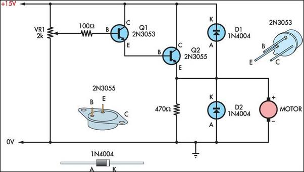
DUE TO WHICH 5V SINGLE IS APPLIED TO NPN TRANSISTOR AND IT GET FIRED AND DUE TO WHICH THE WHOLE 12VDROP SHOULD BE ACROSS MOTOR AND MOTOR GET STARTED. THIS BOT IS BLACK LINE FOLLOWER BUT IF YOU WANT TO MAKE A WHITE LINE FOLLOWER THAN WHAT YOU HAVE TO DO ONLY REPLACE NPN TRANSISTOR BY PNP TRANSISTOR.
🔗 External reference
Warning: include(partials/cookie-banner.php): Failed to open stream: Permission denied in /var/www/html/nextgr/view-circuit.php on line 713
Warning: include(): Failed opening 'partials/cookie-banner.php' for inclusion (include_path='.:/usr/share/php') in /var/www/html/nextgr/view-circuit.php on line 713
