
Two Basic Motor Speed Controllers
DC motor speed controllers are essential components in various applications where precise control of motor speed is required. The two designs mentioned utilize different methods to achieve speed control, which can be beneficial depending on the specific requirements of the application.
The first design employs a Pulse Width Modulation (PWM) technique. In this configuration, a microcontroller generates a PWM signal that modulates the average voltage supplied to the motor. By adjusting the duty cycle of the PWM signal, the effective voltage can be varied, resulting in a change in the motor's speed. This method is highly efficient, as it minimizes power loss and generates less heat compared to other control methods. The circuit typically includes a MOSFET or transistor to handle the current, along with a diode for flyback protection, ensuring that the motor operates smoothly without damaging the components.
The second design utilizes a simple resistive control method. This approach involves placing a variable resistor or potentiometer in series with the motor. By adjusting the resistance, the voltage drop across the motor changes, thereby altering its speed. While this method is straightforward and inexpensive, it is less efficient than PWM control, as it dissipates power as heat in the resistor, which can lead to overheating and reduced lifespan of the components.
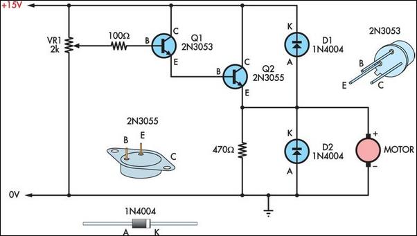
Both designs can be implemented with minimal components, making them cost-effective solutions for controlling 12V DC motors. Careful consideration should be given to the choice of components, such as the rating of the MOSFET or resistor, to ensure they can handle the motor's current without overheating. Additionally, incorporating safety features like fuses or thermal cutoffs can enhance the reliability and longevity of the motor speed controllers.Here are two simple 12V DC motor speed controllers that can be built for just a few dollars. They exploit the fact that the rotational speed of a DC motor.. 🔗 External reference
Related Circuits
The decimal value of the eight input lines is displayed on three seven-segment displays. Although chips exist to perform this function for single displays, none include the capability of displaying numbers greater than 9. No EPROM is necessary in...
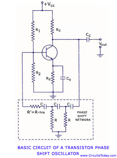
Transistor RC phase shift oscillator. RC phase shift oscillator using operational amplifier. RC phase shift network. Theory and working principle. Circuit diagram. The transistor RC phase shift oscillator is a type of electronic oscillator that generates sine wave signals. This...
This circuit automatically activates and deactivates a motorcycle's headlight, functioning independently of both the light and ignition switches, as long as the battery is fully charged. The initial stage employs a 220-ohm resistor and ZD1 to keep transistor Q1...
The technical parameters of high-speed optocouplers include a rise time (t1) of less than or equal to 300 ns, a circuit transfer ratio (CTR) of 50%, an isolation voltage (VSO) of at least 15,000 V, and an output transistor...
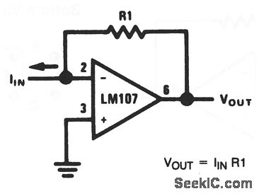
This basic circuit feeds the input current directly into the summing node (pin 2), causing the op-amp output to adjust and extract the same current from the summing node through resistor R1. The scale factor of the circuit is...
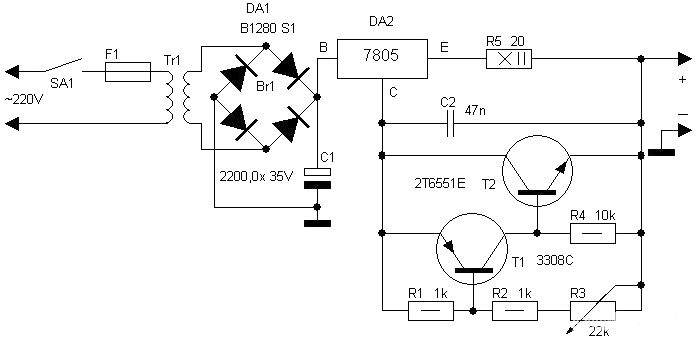
Motorcycle battery charger power supply. Refer to the mentioned page for an explanation of the power supply related circuit diagram. The description of the battery charger indicator: The circuit above enhances the appearance of a simple battery charger, making...