
Remote Control Transmitter Circuit
The transmitter circuit primarily consists of the INS8048L microprocessor, which serves as the central processing unit. It interprets the signals from a keypad interface, generating specific codes that correspond to the keys pressed. The microprocessor is programmed to handle various functions, allowing for flexibility in application, such as remote controls or data transmission.
The generated codes are then modulated onto a 40-kHz carrier frequency, which is essential for efficient transmission of signals over infrared light. Modulation is crucial as it allows the codes to be embedded within the carrier wave, making them suitable for infrared communication.
The output stage of the transmitter includes two infrared light-emitting diodes (LEDs), LED1 and LED2, which are driven by a transistor Q1. This transistor acts as a switch, controlling the current flow to the LEDs based on the signals generated by the microprocessor. The use of two LEDs can enhance the transmission range and reliability, as they can work in tandem to emit a stronger infrared signal.
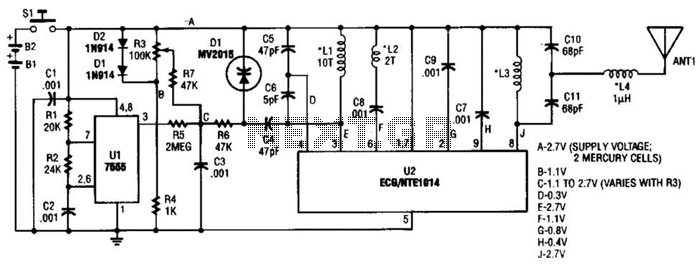
In summary, this transmitter circuit leverages the INS8048L microprocessor for code generation, employs modulation for effective signal transmission, and utilizes infrared LEDs to facilitate communication. This design is suitable for various applications requiring wireless data transmission through infrared signals. This transmitter can be used for a variety of purposes. An INS8048L microprocessor generates various codes depending on keypad presses. The codes are modulated on a 40-kHz carrier. Ql drives IR LEDs LED1 and LED2. 🔗 External reference
Related Circuits

The ADRF6702 TxMod is an IQ modulator that includes an integrated phase-locked loop (PLL) and voltage-controlled oscillator (VCO). The PLL synthesizer employs a fractional-N PLL to produce a 2*FLO input for the I-Q modulator. The PLL reference input can...

A 555 timer configured as an astable multivibrator is used in this circuit to generate an audio note. The capacitance value can be changed to vary the audio note as desired. The circuit utilizes a 555 timer IC, which...
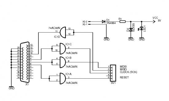
The brain of the robot is composed of an Atmel Tiny2313 microcontroller. This MCU features In-System Programming, allowing programming of its memory using a low-cost programmer. A simple programmer connects to the parallel port and is described in the...
The power supply section is the important one. It should deliver constant output regulated power supply for successful working of the project. A 0-12V/500 mA transformer is used for this purpose. The primary of this transformer is connected in...
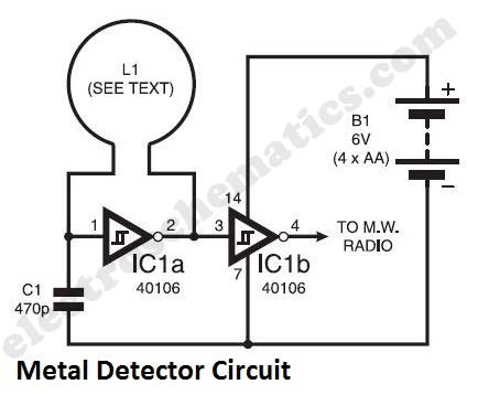
The metal detector circuit presented here exemplifies simplicity while demonstrating effective functionality. It utilizes a single 40106 hex Schmitt inverter IC, a capacitor, a search coil, and batteries. A connection from IC1b pin 4 must be made to a...

400 W MOSFET Audio Amplifier circuit using IRFP448. This circuit is categorized under amplifiers and includes five circuit diagrams. For more detailed information, refer to the main post titled "400 W MOSFET Audio Amplifier Using IRFP448." This post also...