
Simple Metal Detector Circuit

The metal detector circuit operates on the principles of beat frequency oscillation (BFO), where the frequency of the circuit is modulated by the presence of conductive materials. The core component of the circuit, the 40106 hex Schmitt inverter, provides the necessary logic level changes that drive the oscillation. The search coil, which acts as an inductor, is sensitive to changes in inductance caused by nearby metallic objects.
In practical terms, the search coil L1 can be designed with various specifications, but the suggested configuration of seventy turns of 30 SWG enamelled copper wire on a 120mm diameter former provides a good balance between sensitivity and ease of construction. The choice of wire gauge and number of turns directly influences the inductance and, consequently, the frequency response of the circuit.
The output signal from the circuit, which oscillates at approximately 230kHz, is not within the typical range of medium wave radio frequencies. However, the harmonics generated by this oscillation are detectable by an MW radio, allowing users to hear changes in frequency when metal is present. The tuning of the MW radio to a specific harmonic is essential for effective detection, as different harmonics may yield varying levels of sensitivity and clarity.
For enhanced performance, the addition of a Faraday shield can significantly improve the circuit's resilience to external electromagnetic interference. This shield serves to ground unwanted noise and stabilize the circuit's operation.
Overall, this metal detector circuit represents an accessible and educational project for electronics enthusiasts, demonstrating fundamental principles of inductance, oscillation, and frequency modulation while providing practical application in metal detection.The metal detector circuit shown here must represent the limits of simplicity for a metal detector, yet the design works surprisingly well. It uses just one 40106 hex Schmitt inverter IC, a capacitor and a search coil and of course the batteries.
A lead from IC1b pin 4 needs to be attached to a medium wave radio aerial, or it should be wrapped around the radio. It can be used even like those hand held metal detectors. As shown, the metal detector gives a respectable range for beat frequency operation (bfo) up to 90mm for a bottle-top. In fact, for the ultimate in simplicity, capacitor C1 may be omitted. In this way the author achieved am amazing 150mm range for the bottle-top. However, with the frequency then being raised to more than 4MHz, instability becomes a significant problem.
As shown, the circuit oscillates at around 230kHz. One may also experiment with the frequency by changing the value of C1. A Faraday shield may be added to reduce ground effect and capacitive coupling, and this is wired to 0V. Since the inductor resists rapid changes voltage, the charging of C1 is slightly delayed as the logic level at IC1a pin 2 changes.
This sets up a rapid oscillation, which is picked up by a MW radio. Any changes in the inductance of the search coil (through the presence of metal) bring about a change to the oscillator frequency. Although 230kHz is out of range of the Medium Wave band, an MW radio will clearly pick up harmonics of this frequency.
The making of search coil L1 allows a lot of room for error and is far from critical. The author used seventy turns 30 s. w. g. (0, 315mm) enamelled copper wire on a 120mm diameter former. The metal detector is set up by tuning the MW radio to pick up a whistle. Not every such harmonic works well, and the most suitable one needs to be found. The presence of metal will clearly change the tone of the whistle. This is not an industrial or security metal detector and is not even close to loma or eriez metal detection products. It`s just a portable but not a hand held metal detector. 🔗 External reference
Related Circuits
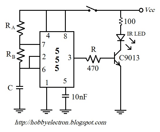
The remote control circuit comprises two main components: a transmitter and a receiver. The transmitter circuit is controlled by an NE555 integrated circuit (IC), while the receiver operates based on the frequency of the signal emitted by the transmitter....
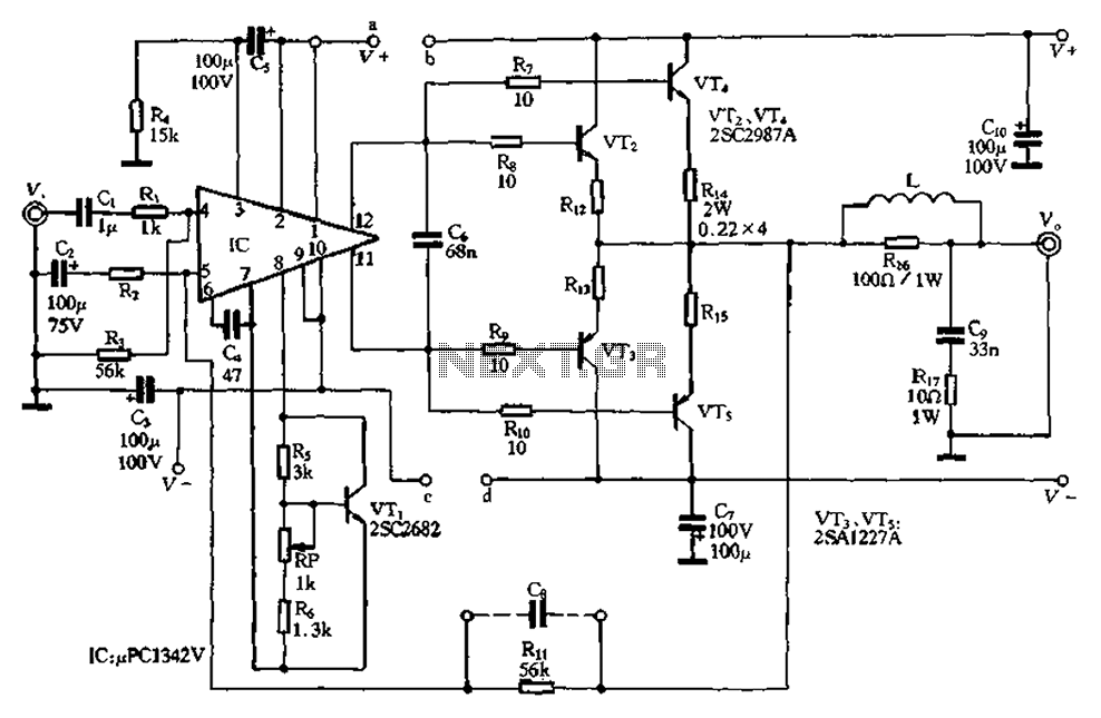
The pLPC1342V and NE are two companies involved in a tube amplifier circuit utilizing 2SA1227A and 2SC2987A transistors, achieving a maximum output power of up to 120W with a cutoff frequency of up to 500 MHz. The circuit, illustrated...

Laptop schematic circuit diagram for laptop repair and laptop BIOS password removal. The laptop schematic circuit diagram serves as a crucial resource for technicians and engineers involved in laptop repair and maintenance. This diagram provides a detailed representation of the...

This circuit is designed to check the peak voltage of a signal that can change at any time. Measuring with a multimeter is insufficient for this purpose, hence the recommendation for this circuit. It operates with a positive signal...
The following circuit illustrates a Solar Tracker Circuit Diagram. This circuit is based on the LM339 integrated circuit. Features include a 10nF ceramic capacitor (103z) and a 1MΩ resistor. The Solar Tracker Circuit utilizes the LM339 quad comparator IC to...
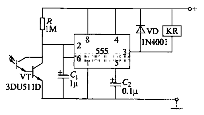
The circuit utilizes a Darlington-type phototransistor as the sensing element, which enhances sensitivity to low light levels, making it suitable for detecting reflected light signals. When the Darlington phototransistor is exposed to light, its resistance decreases, causing the voltage...
Warning: include(partials/cookie-banner.php): Failed to open stream: Permission denied in /var/www/html/nextgr/view-circuit.php on line 713
Warning: include(): Failed opening 'partials/cookie-banner.php' for inclusion (include_path='.:/usr/share/php') in /var/www/html/nextgr/view-circuit.php on line 713