
Remote control using telephone
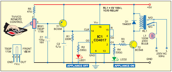
The operation of the circuit begins once a call is established, indicated by the ring-back tone. By dialing '0' in DTMF mode, IC1 decodes this as '1010', which IC2 demultiplexes to output O10 (pin 11). The active low output from IC2, inverted by an inverter gate from IC3 (CD4049), becomes logic high. This signal toggles flip-flop-1 (F/F-1) and energizes relay RL1. Relay RL1 features two changeover contacts: RL1(a) and RL1(b). When RL1(a) is energized, it creates a 220-ohm loop across the telephone line, while RL1(b) injects a 10kHz tone, signaling to the caller that appliance mode is activated. The 220-ohm loop disconnects the ringer from the telephone line, allowing for appliance mode operation. If digit '0' is not dialed in DTMF after the call is established, the phone continues to ring, enabling normal conversation.
When appliance mode is active, dialing '1' is decoded by IC1 as '0001'. This BCD code is then demultiplexed by IC2, with the corresponding output inverted by the CD4049 inverter gate, resulting in a logic high state. This pulse toggles the corresponding flip-flop, which controls relay RL2 to switch the connected appliance on or off. Other appliances can similarly be controlled by dialing their respective digits. Once the switching operations are complete, the 220-ohm loop resistance and 10kHz tone must be removed from the telephone line. This is accomplished by dialing '0' again in DTMF mode, which toggles flip-flop-1 to de-energize relay RL1, thereby removing the loop and the tone. The telephone line is then restored for normal calls. This circuit is designed to be connected in parallel with the telephone instrument.
The schematic representation of this circuit involves a clear layout of the components and their interconnections. The DTMF decoder (IC KT3170) is connected to the telephone line, receiving the DTMF signals. The output of this IC feeds into the demultiplexer (IC 74154), which distributes the decoded signals to the appropriate flip-flops (CD4013). Each flip-flop output is linked to a relay driver circuit, which in turn controls the relays responsible for switching the appliances. The relays are designed to handle the load of the appliances, ensuring safe operation. The inverter (CD4049) is strategically placed to manage the logic levels required for toggling the flip-flops accurately. The circuit also includes necessary power supply decoupling and protection elements to ensure stable operation. Overall, this circuit effectively combines telecommunications with appliance control, offering a versatile solution for remote operation.Here is a teleremote circuit which enables switching on` and off` of appliances through telephone lines. It can be used to switch appliances from any distance, overcoming the limited range of infrared and radio remote controls.
The circuit described here can be used to switch up to nine appliances (corresponding to the digits 1 through 9 of the te lephone key-pad). The DTMF signals on telephone instrument are used as control signals. The digit `0 ² in DTMF mode is used to toggle between the appliance mode and normal telephone operation mode. Thus the telephone can be used to switch on or switch off the appliances also while being used for normal conversation.
The circuit uses IC KT3170 (DTMF-to-BCD converter), 74154 (4-to-16-line demult-iplexer), and five CD4013 (D flip-flop) ICs. The working of the circuit is as follows. Once a call is established (after hearing ring-back tone), dial `0 ² in DTMF mode. IC1 decodes this as `1010 ², which is further demultiplexed by IC2 as output O10 (at pin 11) of IC2 (74154).
The active low output of IC2, after inversion by an inverter gate of IC3 (CD4049), becomes logic 1. This is used to toggle flip-flop-1 (F/F-1) and relay RL1 is energised. Relay RL1 has two changeover contacts, RL1(a) and RL1(b). The energised RL1(a) contacts provide a 220-ohm loop across the telephone line while RL1(b) contacts inject a 10kHz tone on the line, which indicates to the caller that appliance mode has been selected. The 220-ohm loop on telephone line disconnects the ringer from the telephone line in the exchange. The line is now connected for appliance mode of operation. If digit `0 ² is not dialed (in DTMF) after establishing the call, the ring continues and the telephone can be used for normal conversation.
After selection of the appliance mode of operation, if digit `1 ² is dialed, it is decoded by IC1 and its output is `0001 ². This BCD code is then demultiplexed by 4-to-16-line demultiplexer IC2 whose corresponding output, after inversion by a CD4049 inverter gate, goes to logic 1 state.
This pulse toggles the corresponding flip-flop to alternate state. The flip-flop output is used to drive a relay (RL2) which can switch on or switch off the appliance connected through its contacts. By dialing other digits in a similar way, other appliances can also be switched on` or off`. Once the switching operation is over, the 220-ohm loop resistance and 10kHz tone needs to be removed from the telephone line.
To achieve this, digit `0 ² (in DTMF mode) is dialed again to toggle flip-flop-1 to de-energise relay RL1, which terminates the loop on line and the 10kHz tone is also disconnected. The telephone line is thus again set free to receive normal calls. This circuit is to be connected in parallel to the telephone instrument. 🔗 External reference
Related Circuits
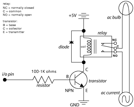
The schematic illustrates the Relay Wiring Circuit Diagram used to control an air conditioner or other high-current devices via a microcontroller. The relay wiring circuit serves as an interface between low-voltage microcontroller signals and high-voltage appliances, such as air conditioners....
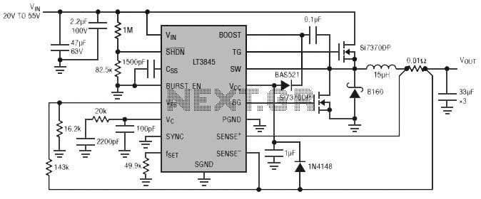
Burst Mode operation maintains high efficiency at light loads by reducing IC quiescent current to 120 µA. Light load efficiency is also improved with the reverse inductor current inhibit function, which supports discontinuous operation. Additional features include an adjustable...
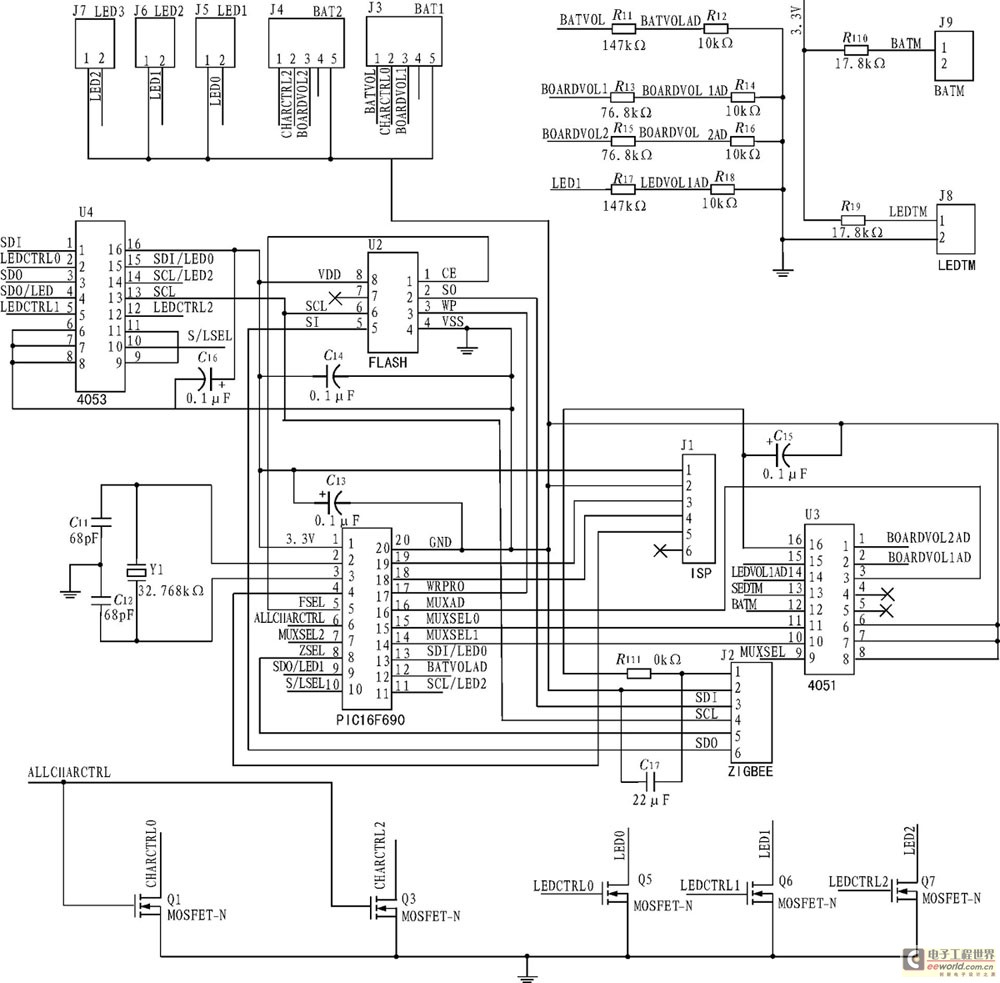
The development of a solar energy street lamp control device has progressed through three stages. The first generation featured a simple and crude function, allowing the light to be turned on or off, but required connection to a light-sensitive...
This page outlines the hardware and software design of a printer power switch that is controlled via USB from a Linksys NSLU2, also referred to as Slug. Although primarily designed for printer control, the unit can manage any device...
It is essential to consider migrating to PIC microcontrollers and exploring compilers such as those offered by Proton Smart, which include Sony IR and Philips RC5 codecs. This approach is particularly advisable for security-sensitive applications. Additionally, Bluetooth and Wi-Fi...
The diagram illustrates the principle circuit of a radio control car receiver. Important notes include the selection of transistor Q1, which is specified as either 1815 or 9018, along with the bias resistor R1, which has values of 240K...
Warning: include(partials/cookie-banner.php): Failed to open stream: Permission denied in /var/www/html/nextgr/view-circuit.php on line 713
Warning: include(): Failed opening 'partials/cookie-banner.php' for inclusion (include_path='.:/usr/share/php') in /var/www/html/nextgr/view-circuit.php on line 713