
A Slug-Controlled Power Switch
The electronic schematic for the printer power switch features the FT245BM USB-to-Parallel interface chip, which serves as the central control unit for the device. The chip connects to the USB port of the NSLU2, allowing it to receive commands from the Linux operating system. The output from the FT245BM is routed to a triac, which is responsible for switching the mains power to the printer. The triac is chosen for its ability to handle AC loads, making it suitable for controlling devices like printers.
To ensure reliable operation, an optocoupler is used to isolate the control signal from the high-voltage side of the circuit. This isolation is crucial for safety, preventing any high-voltage spikes from affecting the low-voltage control circuitry. The selected optocoupler's specifications dictate the necessary current through its input, which in turn influences the design of the surrounding components, such as resistors and capacitors. The RC filter across the triac, consisting of resistor R7 and capacitor C1, smooths out any transients and helps to stabilize the operation during switching events.
The EEPROM integrated within the USB module is essential for defining the device's identity on the USB bus. It stores the vendor and product IDs, which must be programmed correctly to ensure proper communication with the host system. The corresponding software includes routines for reading and writing to the EEPROM, facilitating the configuration process.
In summary, this printer power switch design exemplifies an efficient solution for remotely controlling power to a printer while minimizing energy consumption. The careful selection of components, adherence to electrical safety standards, and integration with existing software frameworks like CUPS enhance the functionality and usability of the device.This page describes the hardware and software design of a printer power switch controlled over USB from my Linksys NSLU2, aka Slug. The unit can, however, be controlled from any Linux box, and can switch anything, not just printers. My NSLU2 acts mostly as a file and print server. I can go for weeks without printing anything, so I want to keep th e printer switched off when I`m not using it (it takes about 4W while idle, which must be more than 99% of its total energy consumption). But it`s upstairs, and I don`t want to have to go up and down stairs once to switch it on and again to collect my printing.
So I decided to get a power switch. There are plenty of power switches out there. Mostly these are expensive things intended for server rooms (see this example ) with RS232 or Ethernet interfaces; USB would be more appropriate for the Slug. One cheap USB switch is this one which has been interfaced to a Slug, but it only seems to be available with continental European sockets.
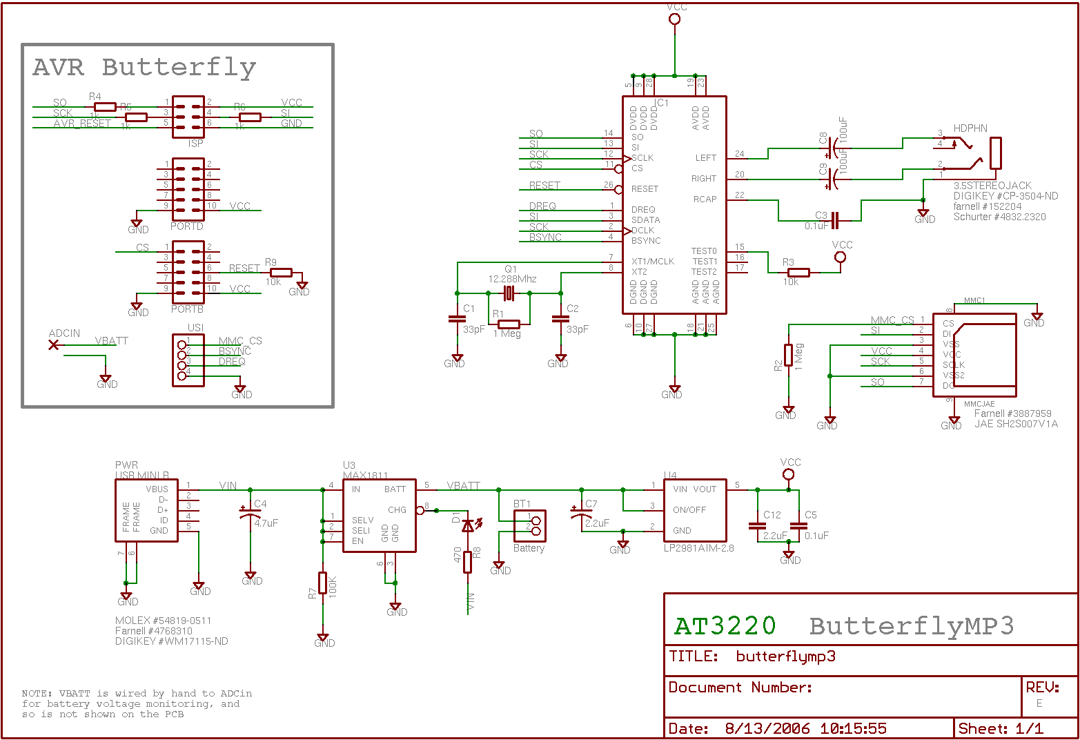
So I decided to build my own. For USB control I decided to use the same USB module that I chose for SlugTerm, using the FT245BM USB-to-Parallel chip. I use just one of its 8 output bits to switch the mains power using a triac. Here`s a photo of my breadboard prototype: I needed to learn a bit about triacs before building the mains side of the circuit.
There is more than you could ever need to know in this document from ON Semi. Here is what I learnt: Triac optocouplers come with various different sensitivities; the K3020P that Maplin sells is the least sensitive and takes 30mA. Futurlec sell more sensitive versions (the K3023P needs only 5mA) which could be driven directly from the USB chip.
Choose R6 based on the optocoupler`s peak surge current: there will be a short time when it has turned on but the main triac hasn`t during which all of the load current will try to flow through it. The last two points are addressed by putting a series RC filter accross the triac (R7 and C1). See the ON Semi document linked above, in particular tables 6. 1 and 6. 3, for the theory and suggested component values. The capacitor needs to be a high voltage type of the order of 0. 047 to 0. 1 uF, and I have found these difficult to obtain: Maplin don`t sell them at all any more, and Futurlec only go up to 0.
01 uF. The 4. 7 nF and 1. 8k that I`ve used seem to work (the circuit is noticeably unreliable without them) but are not ideal. Possible sources include ESR and Rapid Electronics. The USB module contains a small EEPROM which stores USB vendor and product IDs, and this needs to be programmed.
The procedure is identical as for SlugTerm, so I refer you to that documentation rather than repeating it all here. I have chosen vendor EE17 and product 0002. A suitable file for the ftdi_eeprom program is included in the software, see below. You can get the code that I`ve used, as well as the schematics and the EEPROM configuration, using subversion from.
// Slugpower main program // Phil Endecott, July 2006. #include "Ftdi. hh" #include
Related Circuits
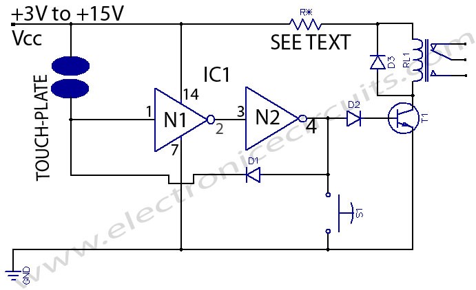
This is a touch switch designed to control LEDs, relays, and similar devices through a buffer transistor stage. It can be constructed using any CMOS inverter chip. The touch switch circuit operates by utilizing the capacitive touch sensing principle, which...
Pictures and a sample schematic (including pinouts) of an AMP hexadecimal (16-position) switch with a screw slot actuator. The AMP hexadecimal switch is a 16-position rotary switch designed for applications requiring multiple selectable options. This switch features a screw slot...
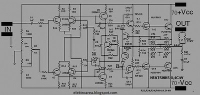
The design of this amplifier aims to enhance the reproduction of complex music and voice. While high electrical properties are emphasized, the primary objective is to achieve superior sound quality, vivid imaging, and exceptional spatial clarity. Although the average...
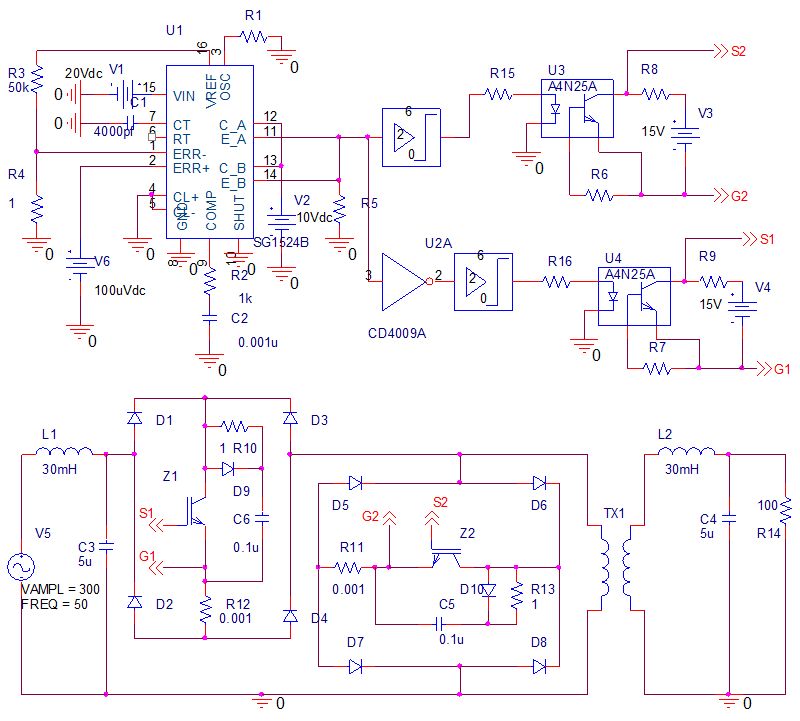
Phase-controlled AC voltage regulator using back-to-back SCRs and diodes, inverse parallel SCRs, and diode-bridge with a single SCR. Input and output voltage waveforms are provided for an input of 250V and an output of 300V. V1 (V5) represents the...

The power supply circuits for servo systems are critical during both the adoption and operational stages. The power supply circuit for servo systems is designed to provide stable and adequate voltage and current levels necessary for the servo motors to...
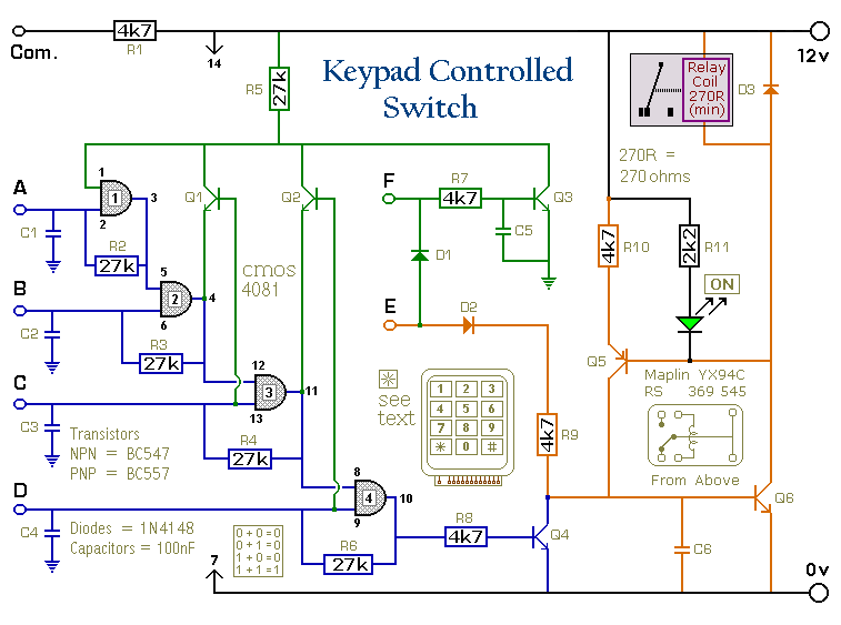
This is a universal version of the Four-Digit Alarm Keypad. The design of the output section has been modified to free up the relay contacts, allowing the circuit to function as a general-purpose switch. A single-pole changeover (SPCO) or...