
Remote Controlled Alarm circuit

The remote-controlled alarm circuit designed with the TSOP1736 is an innovative solution for enhancing safety and convenience, particularly for elderly individuals. The TSOP1736 is an infrared receiver module that effectively detects signals from a compatible remote control. This application allows the user to activate an alarm system from a distance, providing immediate assistance when needed.
The circuit typically includes several key components: the TSOP1736 infrared receiver, a microcontroller for processing the received signals, an alarm module such as a buzzer or siren, and a power supply. When the remote control button is pressed, the TSOP1736 receives the infrared signal and sends it to the microcontroller. The microcontroller interprets the signal and activates the alarm module, which emits a sound to alert caregivers or family members.
In addition to the alarm function, the circuit can be enhanced with features such as LED indicators to show the status of the system, or a more complex interface that allows for different alarm tones depending on the urgency of the situation. The wiring for the calling bell switch should be carefully routed to ensure easy access for the user while maintaining safety standards.
This setup not only promotes independence for the elderly but also ensures that help is readily available at the push of a button. Proper installation and testing of the system are crucial to ensure reliable operation and to avoid any potential issues.A very interesting remote controlled alarm circuit using TSOP1736. Routing of an electric cable to attach a calling bell switch near the bed of an old age/. 🔗 External reference
Related Circuits

Designed to power a low-frequency subwoofer speaker system, the amplifier can deliver up to 100 W into an 8-ohm load. The OPA541BM operational amplifier, produced by Burr-Brown Corporation, necessitates heatsinking for optimal performance. Additionally, the design incorporates a damping...
Circuit Magic is an electrical circuits simulation program specifically designed for students teaching basics electronics, electrical laws & circuit theory. Unlike many electronic circuit analyzers, Circuit Magic can analyze circuits like a man. Circuits are simulated step by step,...
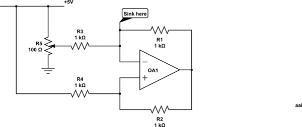
Control a current through several current-mirror devices (specifically the IREF pin on the TLC5940) using a single potentiometer. A modified Howland current source has been utilized, which works adequately with the specified resistor values for dimming an LED. However,...
Make the following connections: GND (pin 8) to ground, Vcc (pin 16) to 5V, OE (pin 13) to ground, MR (pin 10) to 5V. This setup makes all of the output pins active and addressable at all times. The...

A DC solid-state relay (DC-SSR) driving a high-power load circuit is illustrated in (a) below; the high-power load driving circuit is depicted in (b) below. The DC solid-state relay (DC-SSR) serves as a crucial component in controlling high-power loads, providing...

The power supply terminal should utilize a 1 µF chip capacitor filter, positioned as close as possible to the chip's supply pin. The signal is generated by the input pins 2 and 3. The source resistance of the signal...
Warning: include(partials/cookie-banner.php): Failed to open stream: Permission denied in /var/www/html/nextgr/view-circuit.php on line 713
Warning: include(): Failed opening 'partials/cookie-banner.php' for inclusion (include_path='.:/usr/share/php') in /var/www/html/nextgr/view-circuit.php on line 713