
Serial to Parallel circuit Shifting Out with 74HC595
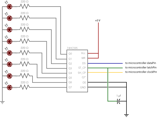
Additionally, 8 LEDs should be added. In this case, the cathode (short pin) of each LED should be connected to a common ground, while the anode (long pin) of each LED should be connected to its respective shift register output pin. Using the shift register to supply power in this manner is referred to as sourcing current. Some shift registers cannot source current and can only sink current. If using such a shift register, the direction of the LEDs must be reversed, connecting the anodes directly to power and the cathodes (ground pins) to the shift register outputs. It is advisable to consult the specific datasheet if a chip other than the 595 series is being used. A 220-ohm resistor should be added in series to protect the LEDs from being overloaded.
The circuit described utilizes a shift register to control multiple LEDs efficiently. The connections to the shift register are critical for ensuring that the correct signals are sent from the Arduino to manage the state of each LED. The ground and power connections to the shift register (pins 8 and 16) establish a common reference point for the circuit, allowing the Arduino to control the output pins effectively.
The output enable (OE) pin, connected to ground, ensures that the outputs are active, while the master reset (MR) pin, connected to 5V, keeps the outputs in a known state upon startup. The data, clock, and latch pins are connected to specific digital pins on the Arduino, allowing for serial data communication to control the state of the LEDs.
When integrating the LEDs, it is crucial to ensure that the correct orientation is maintained. The use of a common ground for the cathodes simplifies the circuit design, while sourcing current through the shift register outputs allows for efficient control of the LEDs. The inclusion of a 220-ohm resistor in series with each LED prevents excessive current flow, protecting the LEDs from damage and ensuring reliable operation.
In summary, this circuit design provides a robust method for controlling multiple LEDs using a shift register in conjunction with an Arduino, allowing for versatile and dynamic lighting effects while ensuring component safety through proper current limiting.Make the following connections: GND (pin 8) to ground, Vcc (pin 16) to 5V OE (pin 13) to ground MR (pin 10) to 5V This set up makes all of the output pins active and addressable all the time. The one flaw of this set up is that you end up with the lights turning on to their last state or something arbitrary every time you first power up the circuit before the program starts to run.
You can get around this by controlling the MR and OE pins from your Arduino board too, but this way will work and leave you with more open pins. DS (pin 14) to Ardunio DigitalPin 11 (blue wire) SH_CP (pin 11) to to Ardunio DigitalPin 12 (yellow wire) ST_CP (pin 12) to Ardunio DigitalPin 8 (green wire) From now on those will be refered to as the dataPin, the clockPin and the latchPin respectively.
Notice the 0.1"f capacitor on the latchPin, if you have some flicker when the latch pin pulses you can use a capacitor to even it out. 3. Add 8 LEDs. In this case you should connect the cathode (short pin) of each LED to a common ground, and the anode (long pin) of each LED to its respective shift register output pin. Using the shift register to supply power like this is called sourcing current. Some shift registers can't source current, they can only do what is called sinking current. If you have one of those it means you will have to flip the direction of the LEDs, putting the anodes directly to power and the cathodes (ground pins) to the shift register outputs.
You should check the your specific datasheet if you aren"t using a 595 series chip. Don"t forget to add a 220-ohm resistor in series to protect the LEDs from being overloaded. 🔗 External reference
Related Circuits
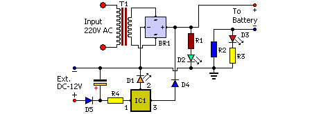
Mobile phone chargers available in the market are quite expensive. The circuit presented here serves as a low-cost alternative to charge mobile telephones or battery packs with a rating of 7.2 volts. The proposed circuit design utilizes a straightforward approach to...

A stepper motor controller based on schematics available on the Arduino website. Initially, a two-pin configuration was attempted for a bipolar stepper motor, but it did not function as expected, especially with the library provided on the site. The...
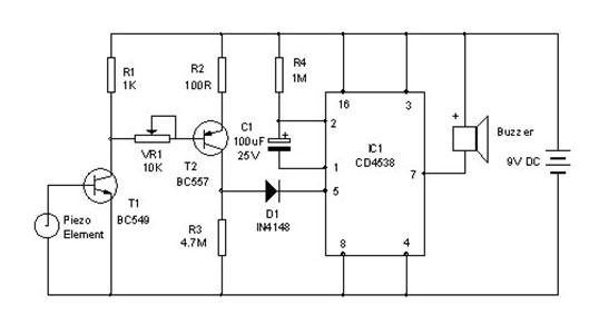
A vibration sensor or piezoelectric vibration sensor circuit diagram. It emits a loud beep when an attempt is made to break a door or window. The alarm automatically ceases after three minutes. The circuit utilizes a piezo element as...

An electronic lock utilizing a telephone key, which is connected through a resistor plug, is integrated after the oscillator circuit's startup phase. The accuracy of the oscillation frequency determines whether the phone can be used for outgoing calls, while...
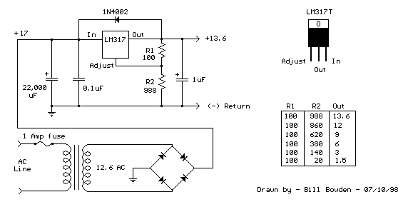
The LM317T is an adjustable three-terminal positive voltage regulator that can supply over 1.5 amps with an output voltage range of 1.25 to 37 volts. It features built-in current limiting and thermal shutdown, making it highly reliable and resistant...

The circuit utilizes a 555 integrated circuit (IC). When an incoming call is received, 220 V AC is stepped down through resistor R1, followed by rectification using diode VD1. A voltage regulator (DW) is employed, and capacitor C2 is...
Warning: include(partials/cookie-banner.php): Failed to open stream: Permission denied in /var/www/html/nextgr/view-circuit.php on line 713
Warning: include(): Failed opening 'partials/cookie-banner.php' for inclusion (include_path='.:/usr/share/php') in /var/www/html/nextgr/view-circuit.php on line 713