
Remote Controlled Fan Regulator

This project involves designing a remote-controlled AC fan regulator that allows users to adjust the fan speed in ten distinct stages. The core of the circuit is based on the ATmega8 microcontroller, which provides the necessary processing power to interpret remote control signals and adjust the fan speed accordingly.
The circuit design includes an infrared (IR) receiver that captures signals from a remote control. The ATmega8 processes these signals to determine the desired fan speed. The microcontroller is programmed to control a triac or a solid-state relay, which in turn regulates the AC power supplied to the fan motor. This method of control allows for smooth speed adjustments, minimizing noise and flicker that can occur with less sophisticated methods.
The PCB layout is designed to accommodate all components, including the microcontroller, IR receiver, power supply circuitry, and the triac or relay interface. Careful attention is given to the placement of components to optimize performance and minimize electromagnetic interference. The source code provided is written in C, utilizing the AVR-GCC compiler, and includes functions for initializing the microcontroller, reading input from the IR receiver, and controlling the output to the fan.
Overall, this project combines both hardware and software elements to create an effective and user-friendly solution for controlling AC fan speeds remotely. The comprehensive documentation ensures that users can replicate the design and understand the functionality of each component within the circuit.A detailed DIY remote controlled AC Fan regulator with 10 stage speed control. Made with ATmega8, full source code and PCB Layout.. 🔗 External reference
Related Circuits
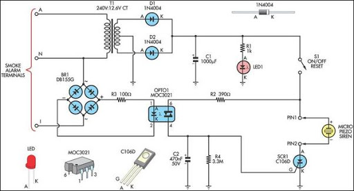
This alarm circuit is designed to monitor a mains-powered smoke detector located in a shed used for dog kennels. It ensures complete isolation from the mains, allowing low-voltage (12V) cabling to run to the alarm circuit, which is situated...
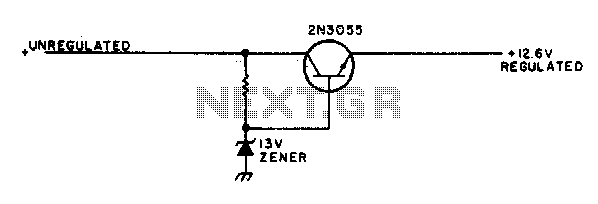
This simple mobile voltage regulator circuit may save your two-meter or CB transceiver if the voltage regulator fails. The 2N3055 should be heat-sinked if the current drawn by the rig exceeds 2 A during transmission. This circuit will do...
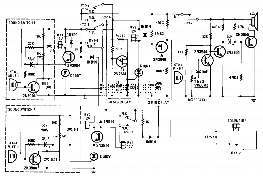
This device monitors sounds in a home or office when a telephone is called from a remote location. The described device functions as an audio monitoring system that activates upon receiving a telephone call. The core of this system typically...
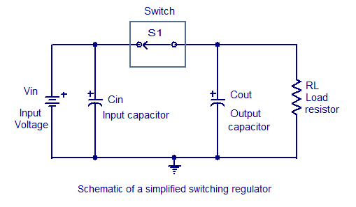
Switching regulators operate by drawing small amounts of energy from the input source and transferring it incrementally to the output. This is achieved using an electronic switch, which functions at a predetermined frequency, acting as a gate between the...
This relay circuit is controlled by nearly any type of infrared remote controller. It operates under the assumption that most remote controllers utilize high-frequency modulated infrared light. By filtering out unmodulated or low-frequency modulated signals, this circuit effectively eliminates...
The circuit is a bistable circuit where each bistable unit is controlled by high and low output levels. When power is supplied to the circuit, current flows through components R13, CL, and VD to VD2 for full-wave rectification. The...