
General Infrared Remote Controlled Relay
This relay circuit provides a versatile method of controlling devices using infrared remote signals. The primary component, the phototransistor, acts as a light sensor that detects the modulated infrared signals emitted by the remote control. The common emitter configuration amplifies the detected signal, allowing for the effective filtering of unwanted noise. The filtering capacitor, C2, plays a critical role in ensuring that only the desired high-frequency signals are processed, which is essential for maintaining the integrity of the relay control.
The operational amplifier IC1 is central to the circuit's performance, with its gain set to 220 times, allowing for significant amplification of the incoming signal. This high gain ensures that even weak signals from the infrared remote can be translated into a usable output for the relay. The negative-feedback network comprising resistors R5 and R2 stabilizes the gain and improves the linearity of the amplifier's response, ensuring that the output remains consistent across varying input levels.
The half-rectifier voltage doubler circuit is designed to convert the amplified AC signal into a usable DC voltage that can energize the relay coil. The choice of a germanium diode in this application is particularly advantageous due to its lower forward voltage drop compared to silicon diodes, resulting in improved sensitivity and responsiveness of the circuit. This is especially important in applications where the infrared signal may be weak or where rapid response times are required.
The relay, represented by RLA, is utilized to control a secondary circuit or device, enabling the operation of various electronic loads based on the infrared signals received. The common-emitter switch configuration, consisting of transistor TR2 and capacitor C2, allows for efficient switching of the relay, providing a reliable method of controlling the connected load.
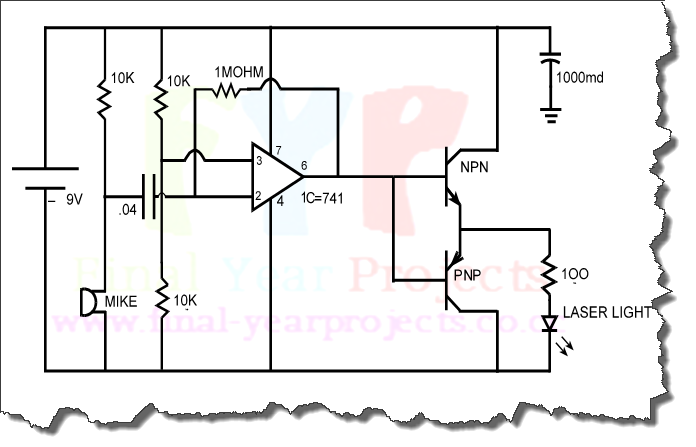
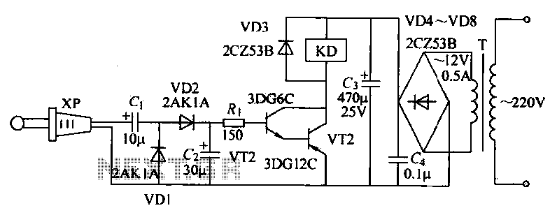
In summary, this relay circuit is an effective solution for interfacing infrared remote controls with various electronic devices, utilizing robust design principles to ensure reliable operation in the presence of potential interference.This relay circuit is controlled by almost any type of infrared remote controller. This circuit works on assumption that almost all remote controller use high frequency modulated infrared light. By filtering out un-modulated or low frequency modulated signal, this circuit will be able to remove any interference from ambient infrared light coming f
rom other sources such as sun light, soldering iron, or incandescent lamps. Here is the schematic diagram of the circuit: This circuit employs a phototransistor which is configured in common emitter amplifier. The C2 does the filtering out of the unmodulated or low frequency signals. The negative-feedback network is formed by R5 an R2. This negative-feedback network set the closed-loop voltage gain of IC1 at 220 times. The amplified output signal from IC1 pin 6 is fed to a half-rectifier-voltage double circuit (D2, C5 and D1).
Since the germanium diode has lower forward voltage drop, the germanim diode is used rather than silicon diode. It increases the sentivity of this circuit. The relay RLA coil is controlled by a simple common-emitter switch which is formed by TR2 and C2. We aim to transmit more information by carrying articles. Please send us an E-mail to wanghuali@hqew. net within 15 days if we are involved in the problems of article content, copyright or other problems.
We will delete it soon. 🔗 External reference
Related Circuits
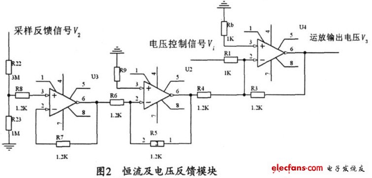
The output current range of the parameter current regulator is limited, and its precision is not high. Connecting the feedback adjustment type output current of the current-stabilized power source in series results in lower efficiency. The steady current source...
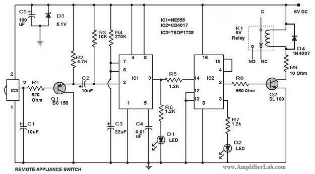
The circuit diagram of a remote-controlled appliance switch circuit includes two main components: IC1 (NE 555) and IC2 (CD 4017). The remote-controlled appliance switch circuit is designed to allow users to control electrical appliances wirelessly. The heart of this circuit...
The objective of this project is to design a circuit for an electronic infrared communication system, develop innovative ideas for implementing this circuit, and study the circuitry along with various components such as DTMF generators, DTMF decoders, operational amplifiers,...
This compact Infrared Remote Control Tester circuit is designed to verify the functionality of an infrared remote control unit. The circuit operates by connecting a piezo buzzer directly to an IR receiver integrated circuit (IC). The TSOP1738 integrated IR...
Instructions for utilizing an existing infrared transmitter from any room within the house. The concept is straightforward and operates more effectively than anticipated. This project proves to be quite useful, allowing control over devices from virtually anywhere. For instance,...
The receiver circuit depicted in the figure requires the insertion of a plug into the radio headphone jack. When the radio receiver detects a signal from the transmitter, an audio signal is output from the jack. This signal is...