
Remote Alarm For Smoke Detector

The alarm circuit operates by monitoring the smoke detector's output signal, ensuring a reliable response to smoke detection events. The use of a bridge rectifier (BR1) allows for effective conversion of the AC signal from the smoke detector into a usable DC signal, which is essential for the subsequent processing stages. The opto-isolator (OPTO1) provides electrical isolation between the smoke detector and the alarm circuit, enhancing safety and preventing potential damage from voltage spikes.
The SCR (Silicon Controlled Rectifier) serves as a switch that is triggered by the opto-isolator, allowing current to flow to the piezo siren. This design choice enables the alarm to produce a loud sound, alerting individuals in the vicinity of potential danger. The inclusion of a transformer (T1) and full-wave rectifier (D1 and D2) ensures that the circuit operates safely at low voltage, minimizing risks associated with mains power.
Capacitor C1 plays a critical role in stabilizing the power supply, filtering out any noise that may affect the performance of the circuit. The LED (LED1) provides a visual indication of circuit status, allowing users to easily determine if the system is powered and operational.
The latching mechanism of the alarm ensures that once triggered, the alarm remains active until manually reset, which can help in preventing false alarms due to transient signals. The option to connect a relay provides versatility in the circuit's application, enabling it to control additional devices, such as emergency lighting systems, thereby enhancing safety measures in case of smoke detection. This comprehensive design not only prioritizes functionality but also safety, making it suitable for monitoring environments where smoke detection is critical.This alarm circuit was designed to monitor a mains-powered smoke detector located in a shed (which is used to house dog kennels). It provides complete isolation from the mains so that low-voltage (12V) cabling could be run to the alarm circuit which is located inside the house.
In operation, the alarm signal (I) from the smoke detector is rectifie d using bridge rectifier BR1 and then fed to optoiso lator OPTO1 via resistor R3. This in turn drives the gate of SCR1 which turns on and activates a piezo siren with inbuilt oscillator. Power for the circuit is derived via mains transformer T1. This drives a full-wave rectifier based on diodes D1 & D2 to produce around 9V DC and this is then applied to the alarm cir cuit via switch S1.
Capacitor C1 filters the supply rail, while LED1 provides power-on indication. When the alarm is triggered, it latches on until reset by S1 (ie, the switch must be opened and then closed again). Finally, a relay could be connected between pins 1 & 2 to switch larger loads than the piezo siren - eg, to turn emergency lights on.
🔗 External reference
Related Circuits

This alarm features both open-loop and closed-loop detection systems along with an automatic alarm shutoff mechanism. It provides a 15-second delay for exit and entrance. Additionally, the alarm activation time can be adjusted from 1 to 15 minutes. The alarm...
This simple circuit using a single transistor turns ON the relay when light falls on the LDR. The potentiometer is adjusted for the required sensitivity. The power supply is 6V. Be careful about the impedance of the relay. Its...

A schematic diagram for the remote analyzer is presented. The circuit operates from a basic 5-V power supply, which includes components PL1, S1, T1, a bridge rectifier made up of diodes D1 through D4, capacitor C1, and a common...
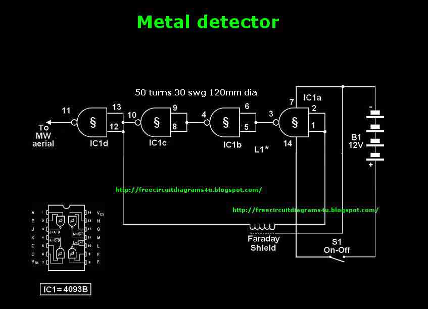
This circuit needs a Faraday shield, which is connected to 0V. To make this one wrap a tin foil around the coil and connect to 0V. Then you can use this circuit to find metal. Tune your mw radio...

Variable resistor R1 adjusts the light threshold at which the circuit triggers. R1's value is chosen to match the photocell's resistance at darkness. The circuit uses a CMOS 4001 IC. Gate U1a acts as the trigger, U1b and c...
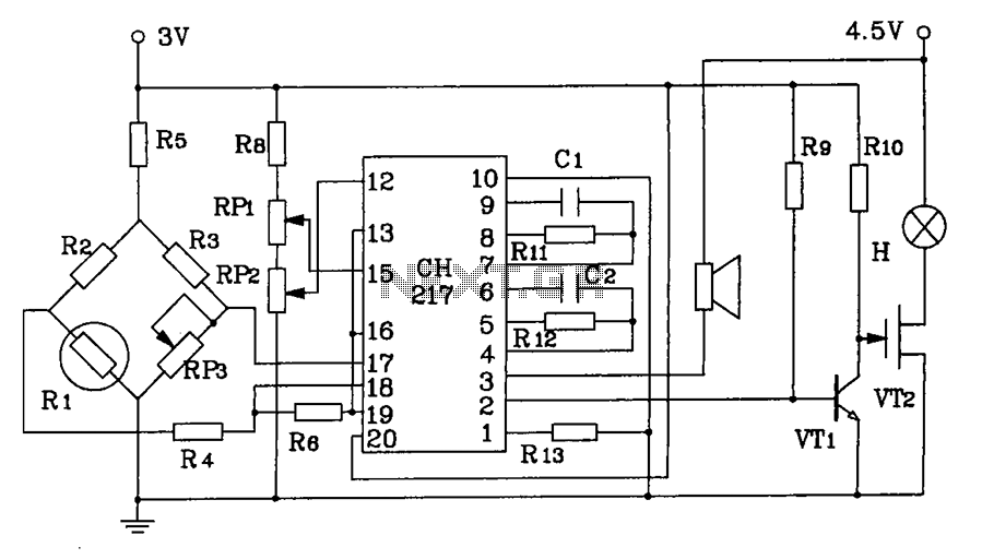
CH217 is a monolithic gas detection alarm integrated circuit. The gas detection alarm circuit diagram includes R1 as the gas sensing probe, where the resistance increases as the gas concentration decreases linearly. RP3 is used to adjust the output...
Warning: include(partials/cookie-banner.php): Failed to open stream: Permission denied in /var/www/html/nextgr/view-circuit.php on line 713
Warning: include(): Failed opening 'partials/cookie-banner.php' for inclusion (include_path='.:/usr/share/php') in /var/www/html/nextgr/view-circuit.php on line 713