
Remote controlled LED
The operation of a remote control system begins with the transmission of encoded signals, which are generated when a user presses a key on the remote. These signals can either be in the form of radio frequency (RF) waves or infrared (IR) light pulses. The choice between RF and IR depends on the application, with RF commonly used in gate openers and alarms, while IR is prevalent in consumer electronics like TVs and DVD players.
Upon pressing a key, the corresponding code is transmitted repeatedly to ensure reliable reception. The receiver, typically an integrated circuit (IC) or a miniature module, captures these signals. The receiver is designed to operate with a low power supply, usually around 5V, and features multiple pins for various functions. These pins may include an aerial input for RF signals, additional power lines, and test signal outputs, alongside a ground connection.
The TSOP1836 infrared receiver IC exemplifies a simple yet effective component for IR applications. It has three essential pins: one for the power supply, one for ground, and one for outputting the decoded signal. The output pin connects directly to the input of a remote control decoder, such as the one found in Nutchips. This decoder interprets the logic pulse train generated by the receiver, which consists of binary signals representing the original key presses.
The decoder is capable of distinguishing between multiple keystrokes, specifically up to eight different inputs. Users can configure which six of these keys will be active, allowing for flexible control options. The integration of a pull-up resistor within the decoder circuit ensures that the output remains high when no signals are detected, eliminating the need for external components.
In summary, the combination of a remote control, a receiver like the TSOP1836, and a decoder such as the one found in Nutchips creates a robust system for wireless communication, enabling the control of various electronic devices through simple key presses.The remote control transmits encoded signals. Each time a key is pressed, the relevant code is transmitted, usually repeating it many times to ensure reception. This encoded signals travels over a radio or infrared-light beam, to eventually get captured by the receiver.
The receiver includes a sensitive circuit capable to transform those weak radio-clicks or infrared flashes in an electric signals with only two logic levels, zero and ones. The logic levels appear as train pulses relfecting the original code: they conneot be used directly, as the need to be decoded in order to determine which key was origianally pressed.
Remote controls are easy to get as spare parts for TV sets and gate openers. The fall in two categories, infrared (TV, HiFi, VCR, DVD) and radio frequency (gate openers, alarms). The former can be found in supermarkets also as "universal" remotes, capable of emulating almost all of known codes.
Receivers are specialized integrated circuits or miniature modules. They usually require just a 5V power supply to work, with three or more pins. Apart power supply, the extra pins can carry test signal, separate power lines, aerial input for RF (radio frequency) receivers, or be just NC (not connected) pins. The output signal is a logic pulse train consisting of zeroes and ones, ready for the decoding stage.
nce again, we start from the LED flasher circuit from our previous articles in this mini-course; we are going to add an infrared receiver IC, a TSOP1836. This integrated circuit manufactured by Temic/Vishay is very simple to use, as its only three pins must connect to the positive power supply (+5V), negative (GND), and remote control decoder (OUT).
The receiver's output connects to Nutchip's remote control decoder input, namely the REMOTE pin (pin 6). The manufacturer specifies a pull-up resistor to keep this output positive when no signal are received: the REMOTE input integrates this resistor therefore it is no longer necessary to add it externally.
A decoder is integrate inside Nutchips, its input connected to REMOTE pin (pin 6). It is suitable for decoding either RF or infrared signals, and can recognize up to 8 different key strokes. You can cselect which 6 keys to decode among the many a remote control can offer. Keystrokes (identified by key1, key2,... key8) can be inserted into truth tables, as they were real keys connected to Nutchips inputs. 🔗 External reference
Related Circuits
This circuit enables the remote switching of appliances via telephone lines. It allows for the control of appliances from any distance, surpassing the limitations of infrared and radio remote controls. The design accommodates up to nine appliances, corresponding to...
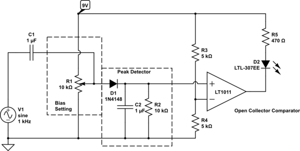
Control an LED with an audio signal; however, the output signal is only 150 mV peak-to-peak (with a 150 mV positive offset). It is understood that a higher voltage than 0.6 V is required to activate the transistor, leading...
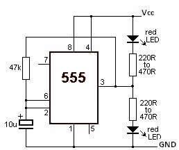
This LED flasher circuit utilizes the 555 timer integrated circuit (IC). The circuit diagram is straightforward and requires only a few external components. When operational, the red LEDs will flash sequentially at a predetermined frequency, similar to the indicators...
The receiver circuit and display module will receive the high-frequency AC power cord and decode it to provide actual temperature readings using digital IC No. CD4553 (Three-digit BCD Counter IC) and IC CD4511 (BCD-to-7-Segment Latch/Decoder/Driver IC). The frequency pulses...
A brief history: Like many tutorials, this one begins with a historical overview. However, it must be noted that there is limited background information available regarding the development of 7-segment displays. 7-segment displays are widely used electronic components that...
This project has two advantages over previous dice circuits. It produces a realistic readout as well as a slow-down feature. These combine to make it one of our most popular games projects. As can been seen in the photo,...
Warning: include(partials/cookie-banner.php): Failed to open stream: Permission denied in /var/www/html/nextgr/view-circuit.php on line 713
Warning: include(): Failed opening 'partials/cookie-banner.php' for inclusion (include_path='.:/usr/share/php') in /var/www/html/nextgr/view-circuit.php on line 713