
Remote On-Off Switch through Small Transformer
The remote on-off switch circuit operates by utilizing a low-power control signal to manage a high-power load. Typically, the circuit consists of a transmitter and a receiver. The transmitter is connected to a small switch, which can be activated remotely. When the switch is pressed, it sends a signal to the receiver unit.
The receiver is often composed of a relay or a solid-state switch, which is capable of handling the high AC voltage and current required by the connected device. The relay or switch acts as a bridge, allowing or interrupting the flow of electricity to the high-power device based on the control signal received from the transmitter.
Key components in this circuit may include:
1. **Transmitter Unit**: This may consist of a simple RF transmitter circuit that encodes the switch signal and transmits it wirelessly.
2. **Receiver Unit**: This includes an RF receiver circuit that decodes the incoming signal and activates the relay.
3. **Relay**: A relay with appropriate ratings to handle the AC load is necessary. The relay coil is energized by the receiver output, closing the contacts and allowing current to flow to the connected device.
4. **Power Supply**: A suitable power supply for both the transmitter and receiver circuits, ensuring that they operate within their specified voltage and current ratings.
Safety measures should be considered, such as using opto-isolators to separate control and power circuits, and ensuring that the relay is rated for the specific load to prevent overheating or failure during operation. This circuit design is widely used in applications where remote control of appliances is desired, providing convenience and efficiency in managing power consumption.This is a remote on-off switch circuit. With this circuit, we can take the benefit of using small switch to control larger AC current from high power devices.. 🔗 External reference
Related Circuits
This is a license to use the files to manufacture up to 12 boards. If additional boards are required, please make contact. It is important to note that the order must specify the intent to produce 12 or fewer...
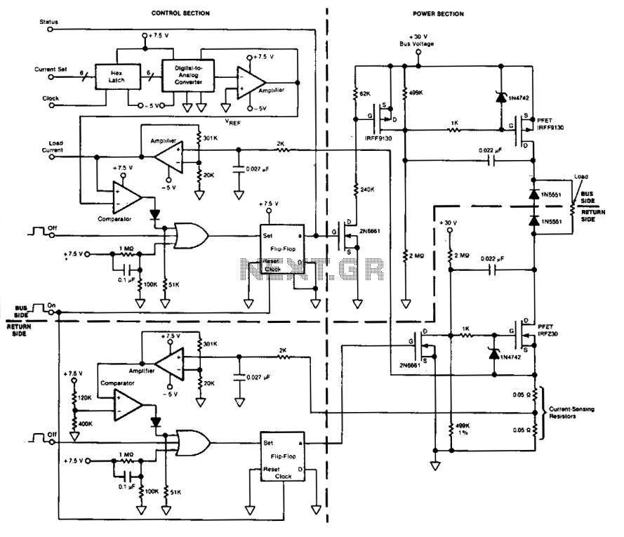
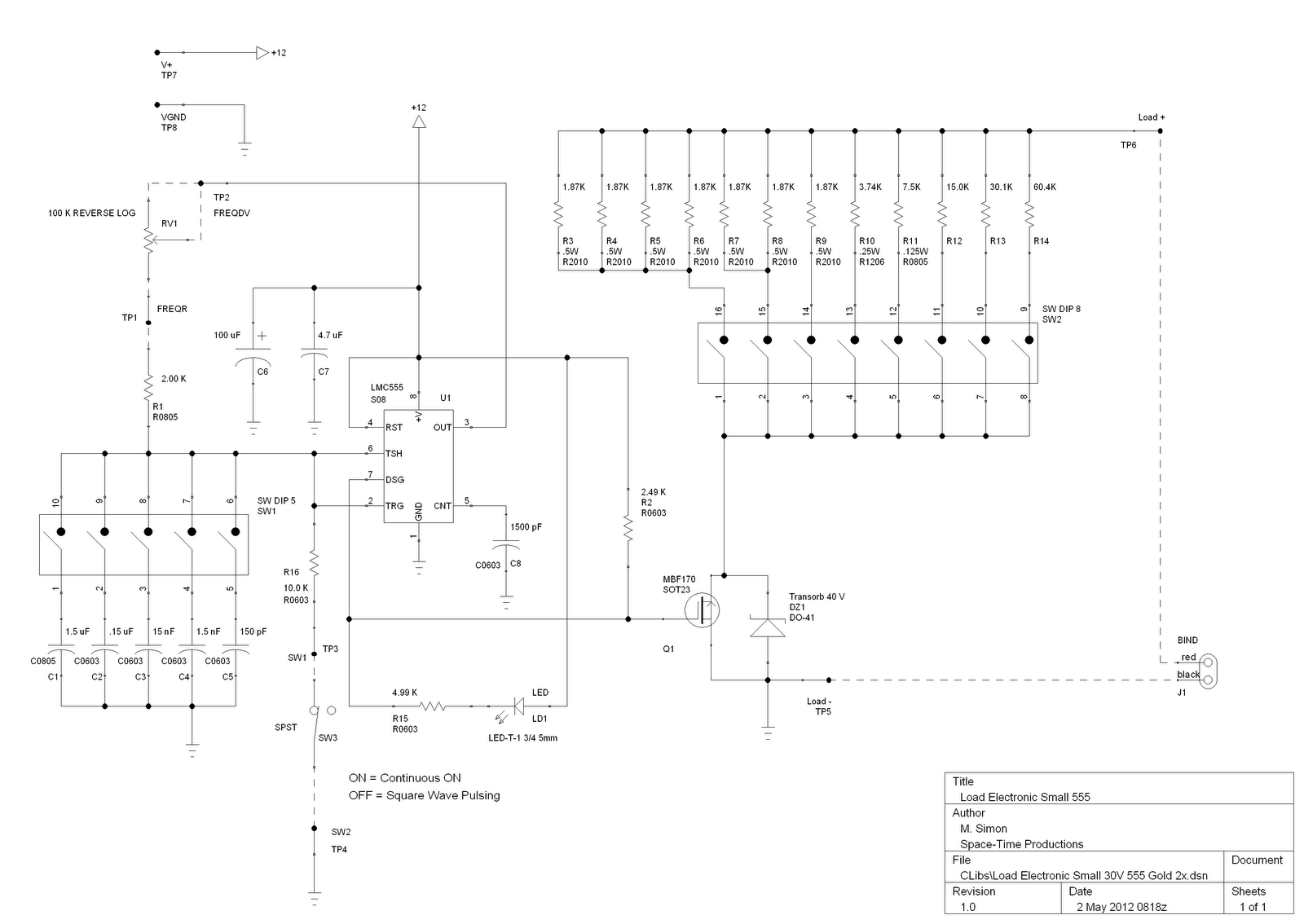
This circuit facilitates on/off switching, soft starting, current monitoring, current tripping, and overcurrent protection for a 30 Vdc power supply, accommodating normal load currents of up to 2 A. The switch is activated by an "on" command pulse and...
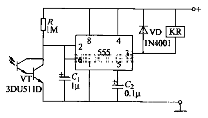
The circuit utilizes a Darlington-type phototransistor as the sensing element, which enhances sensitivity to low light levels, making it suitable for detecting reflected light signals. When the Darlington phototransistor is exposed to light, its resistance decreases, causing the voltage...
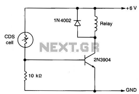
The resistance of the CDS cell decreases when exposed to light, activating the 2N3904 relay driver. The circuit utilizes a Cadmium Sulfide (CDS) photoresistor, which is a light-dependent resistor that changes its resistance based on the intensity of light...
This is a straightforward tester designed to verify the fundamental operations of an infrared remote control unit. It is cost-effective and simple to assemble. The tester utilizes the infrared receiver module TSOP1738. The operation of the remote control is...
Normally, home appliances are controlled using switches, sensors, etc. However, physical contact with switches may be dangerous if there is any shorting. The circuit described here requires no physical contact for operating the appliance. It only requires moving a...
Warning: include(partials/cookie-banner.php): Failed to open stream: Permission denied in /var/www/html/nextgr/view-circuit.php on line 713
Warning: include(): Failed opening 'partials/cookie-banner.php' for inclusion (include_path='.:/usr/share/php') in /var/www/html/nextgr/view-circuit.php on line 713