
Sensitive light control switch circuit
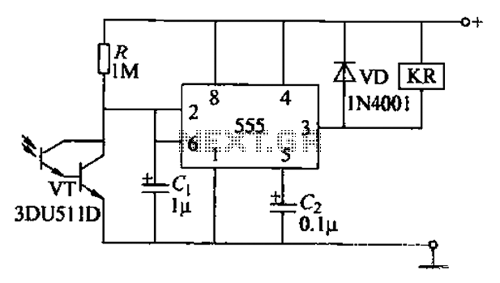
The described circuit employs a Darlington pair configuration for the phototransistor, which consists of two bipolar junction transistors (BJTs) arranged to provide high current gain. This configuration is particularly advantageous for applications requiring detection of low light levels, as it allows for greater amplification of the small currents generated by the phototransistor when exposed to light.
The operation begins when ambient light strikes the phototransistor, resulting in a decrease in its resistance. This change in resistance leads to a corresponding drop in voltage at the output pin of the circuit. The circuit is designed with a specific threshold voltage (U) such that when the output voltage falls below U divided by three (U/3), it triggers the relay. The relay serves as a switching device that can control larger loads, thus enabling the circuit to interface with external devices or systems.
The components of the circuit may include a power supply, resistors to set the biasing conditions of the phototransistor, and capacitors for stability and noise filtering. Additionally, the relay may be accompanied by a flyback diode to protect the circuit from voltage spikes generated when the relay coil is de-energized.
In summary, this circuit effectively utilizes a Darlington-type phototransistor for low light detection and relay activation, providing a reliable solution for applications requiring reflected light sensing.As a result of the circuit shown in Darlington type phototransistor as the sensing element, the more sensitive to low light, suitable for the reflected light detection signal. Circuit, when Darling Introvert phototransistor exposed to light, its resistance decreases, so that the potential of pin fall, when reduced to U [ c/3. feet high output, then the relay releases.
Related Circuits
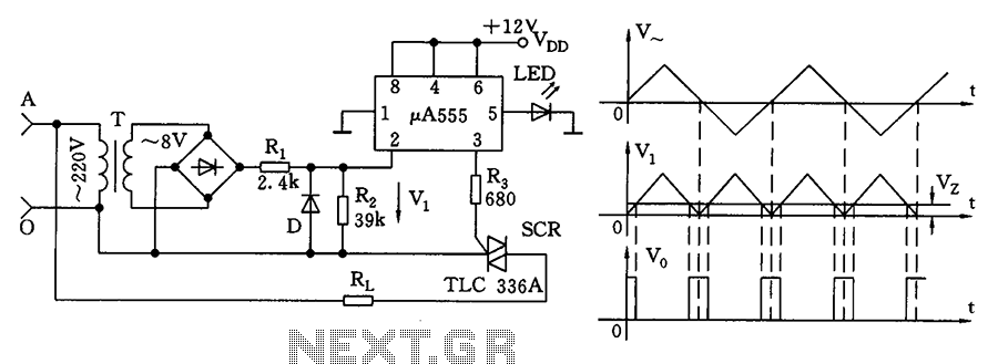
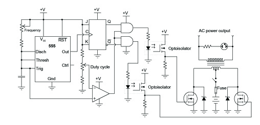
The zero volt switching circuit generates a trigger pulse at the zero crossing of the AC voltage. To facilitate this, the zero crossing of the 555 limit comparator is connected to a single form, with the comparison voltage set...
This circuitry provides a magnification of 1,200,000 times, with a bandwidth ranging from 0.5 to 14 MHz. The input impedance is 700 ohms, while the output impedance is 35 ohms when measured at 5 MHz. The output noise level...
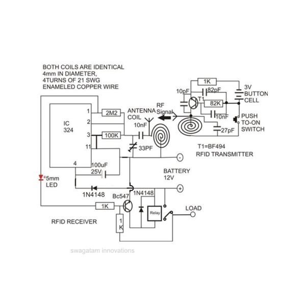
Constructing an RFID access control circuit at home and witnessing its functionality can be a remarkable experience. While the circuit may not be considered high-tech, its low cost combined with the satisfactory results achieved demonstrates a significant level of...
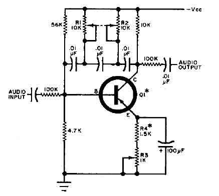
This circuit is designed for selective tuning adjustments between two closely spaced audio tones. The frequency is determined by the values of the capacitors and resistors in the feedback circuit connecting the collector and base of transistor Q1. With...
A common topology for DC-AC power converter circuits employs a pair of transistors to switch DC current through the center-tapped winding of a step-up transformer. Examine the check plot images from a PCB drafting program for a control board...
The proximity detector detects the movement of PC board pieces as the wheel rotates, generating an output signal with a clear transition between high and low voltage levels, making it suitable for triggering counting or processing circuits. Following this...