
Wireless On-Off Switch
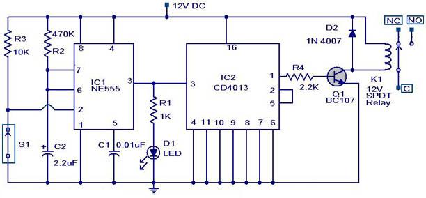
The described circuit utilizes an infrared LED and a phototransistor to create a non-contact control mechanism for various home appliances. The key components, including the CA3140 operational amplifier, serve to amplify the signal detected by the phototransistor, enhancing the circuit's sensitivity and reliability. The infrared LED (D2) emits a continuous beam of infrared light, which is typically invisible to the human eye. When a hand is moved within the path of this infrared beam, it interrupts the light reaching the phototransistor (Q1), triggering a change in the output state of the circuit.
The operational amplifier (IC1) is configured in a non-inverting mode, where the voltage at pin 3 (non-inverting input) is influenced by the signal from the phototransistor. The voltage at pin 2 (inverting input) is set by the voltage-divider network formed by resistor R4, which allows for fine-tuning of the sensitivity. This adjustment is crucial for ensuring that the phototransistor can detect even slight interruptions in the infrared beam, thus enabling reliable operation of the appliance.
Transistor Q2 (BC548) acts as a switch, controlled by the output of the operational amplifier. When the output at pin 6 of IC1 goes high due to the interruption of the infrared beam, Q2 is activated, allowing current to flow through the relay (RL1). This relay, in turn, can control higher voltage AC appliances safely, isolating the low-voltage control circuit from the mains voltage.
The low current consumption of the circuit makes it suitable for battery-operated applications, while its compact design allows for easy integration into various appliances. The simplicity of the circuit layout and the use of commonly available components further enhance its practicality for DIY projects or commercial applications. Proper assembly on a general-purpose PCB, along with careful attention to component orientation and soldering, will ensure the circuit operates as intended.Normally home appliances are controlled by means of switches, sensors, etc. However, physical contact with switches may be dangerous if there is any shorting. The circuit described here requires no physical contact for operating the appliance. You just need to move your hand between the infrared LED (D2) and the phototransistor (Q1). The infrared rays transmitted by D2 is detected by the phototransistor to activate the hidden lock, flush system, hand dryer or else. This circuit is very stable and sensitive compared to other AC appliance control circuits. It is simple, compact and cheap. Current consumption is low in milliamperes. The circuit is built around an IC CA3140, D2, phototransistor and other discrete components. When regulated 5V is connected to the circuit, D2 emits infrared rays, which are received by phototransistor Q1 if it is properly aligned.
The collector of Q1 is connected to non-inverting pin 3 of IC1. Inverting pin 2 of IC1 is connected to voltage-divider preset R4. Using preset R4 you can vary the reference voltage at pin 2, which also affects sensitivity of the phototransistor. Op-amp IC1 amplifies the signal received from the phototransistor. Resistor R3 controls the base current of transistor BC548 (Q2). The high output of IC1 at pin 6 drives transistor Q2 to energies relay RL1 and switch on the appliance, say, hand dryer, through the relay contacts.
The working of the circuit is simple. In order to switch on the appliance, you simply interrupt the infrared rays falling on the phototransistor through your hand. During the interruption, the appliance remains on through the relay. When you remove your hand from the infrared beam, the appliance turns off through the relay. Assemble the circuit on any general-purpose PCB. Identify the resistors through colour coding or using the multimeter. Check the polarity and pin configuration of the IC and mount it using base. After soldering the circuit, connect +5V supply to the circuit. 🔗 External reference
Related Circuits
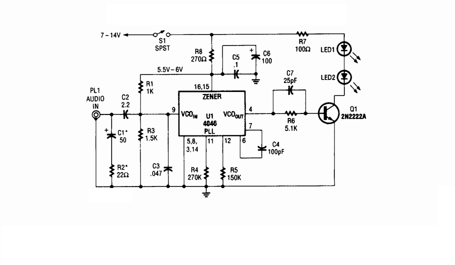
Wireless infrared headphone transmitter. Audio input from PL1 frequency modulates the voltage-controlled oscillator (VCO) section of a 4046 phase-locked loop (PLL) chip. The VCO output drives Q1, a switching transistor, which in turn drives two infrared (IR) LEDs. The wireless...
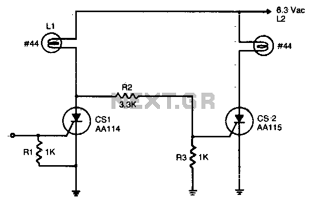
An input signal of less than 1 mA and 1V is required to switch on CS1. As long as this input signal is maintained, CS1 will conduct during each positive half-cycle of anode voltage, thereby energizing load L1 with...
A circuit that will find enough applications. Basically, the designing became in order to exist delay in quench one or more lamps in a stairwell or in any other space exists this need. It can become use for the...
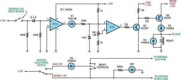
The current vehicle, a Pajero, has been modified for dual fuel operation, utilizing both petrol and gas. It is essential to operate the vehicle on petrol at regular intervals to prevent clogging of the injectors. This circuit facilitates starting...
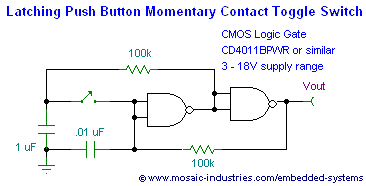
This page presents soft power switch circuits designed for toggling electronic devices ON and OFF with a momentary button press that controls a latching high-side MOSFET power switch. Multiple micropower latching switch circuits are included. Due to their low...
A magnetic switch is a circuit designed to respond to surrounding magnetic fields detected by the sensor. This series of magnetic switches employs limit switch sensors that include an additional metal plate capable of responding to a magnet. The...