
Remote Operated Spy Robot Circuit

The remote-operated spy robot circuit is designed for efficient surveillance applications, integrating audio and video capturing capabilities with robust wireless communication. The system architecture includes a microcontroller interfaced with the HT 12E encoder, which processes inputs from a remote control. The DIP switches allow for easy configuration of the device's unique address, ensuring that multiple units can operate in proximity without interference.
The 433MHz ASK transmitter and receiver modules are key components in this design, providing reliable communication over a distance of up to 125 meters. The transmitter's compact size and low power requirements make it suitable for portable applications, while the H-bridge motor driver circuit enables precise control of the two DC gear motors, allowing for smooth movement of the robot.
The integration of a camera allows for real-time audio and video streaming, enhancing the robot's functionality. The captured signals can be transmitted wirelessly to a remote monitoring station, where they can be processed and displayed using standard TV receivers or computers equipped with tuner cards. This capability makes the robot an effective tool for reconnaissance and surveillance tasks, providing users with critical information from a safe distance.
Overall, the design emphasizes modularity and ease of use, making it accessible for hobbyists and professionals alike. The use of widely available components ensures that the circuit can be replicated and modified for various applications, further extending its utility in the field of remote surveillance technology.Here is a remote operated spy robot circuit which can be controlled by using a wireless remote controller. It can capture audio and video information`s from the surroundings and can be sent to a remote station through RF signals.
The maximum range is 125 meters. It overcomes the limited range of infrared remote controllers. This robot consists of mainly two sections. They are explained in detail below. The circuit uses HT 12E, HT 12D encoder and decoder. 433MHz ASK transmitter and receiver is used for the remote control. H-bridge circuits are used for driving motors. Two 12V DC/100RPM gear motors are used as drivers. The working of the circuit is as follows. When we are pressing any key in remote controller the HT 12E generate 8 bit address and 4 bit data. The DIP switches are used for setting the address. Then the ASK transmitter sends the 8 bit address and 4 bit data to the receiver Then the ASK receiver receives the 8 bit address and 4 bit data and HT 12D decoder decodes the data, thus enabling the appropriate output. Thus the output signals that are generated controls the H-bridge which then rotates the motors. The 433 MHZ ASK transmitter and receivers are extremely small, and are excellent for applications requiring short-range RF remote controls.
The transmitter module is only 1/3rd the size of a standard postage stamp, and can easily be placed inside a small plastic enclosure. The transmitter output is up to 8mW at 433. 92MHz. The transmitter accepts both linear and digital inputs and can operate from 1. 5 to 12 Volts-DC, and makes building a miniature hand-held RF transmitter very easy. The 433 MHZ ASK transmitters is approximately the size of a standard postage stamp The 12 Volt DC supply is taken from the battery placed in the robot.
The camera has a receiver, which is placed in the remote station. Its output signals are in the form of audio and video. These signals are directly connected to a TV receiver or a computer through a tuner card. 🔗 External reference
Related Circuits
Over-Temperature Alarm Circuit Uses Common, Inexpensive Components | Negative-temperature-coefficient (NTC) thermistor, ICs. The Over-Temperature Alarm Circuit is designed to detect excessive temperatures and provide an alert using readily available and cost-effective components. The core sensing element of this circuit is...
When the detect subroutine is invoked, it initially waits for a start bit. The duration of the low segment of the first start bit is measured. If the low pulse of the first start bit exceeds 1.020 ms or...
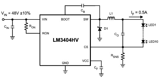
The LM3404 is a monolithic switching regulator that can be utilized to design a simple constant current driver for high-power LEDs. This LED driver project is suitable for automotive, industrial, and general lighting applications. Hysteretic control of the on-time,...
A thermistor positioned as indicated creates a heat-activated sensor. Variations in temperature will modify the output of the operational amplifier, triggering the relay and illuminating the LED. Reversing the placement of the thermistor and the 47k resistor converts the...

It is embarrassing to acknowledge that the blog post from April 29 contained several schematic errors of my own making, particularly in the variation of Morgan Jones's circuit. One of the resistor values was incorrect by a factor of...

A DC-coupled multi-stage amplifier circuit consists of multiple stages of amplification using a DC-coupled configuration. Each stage utilizes NPN-type transistors, which are designed to maintain appropriate operating points at the base of each stage. As the signal progresses through...