
Over-Temperature Alarm Circuit Uses Common Inexpensive Components
The Over-Temperature Alarm Circuit is designed to detect excessive temperatures and provide an alert using readily available and cost-effective components. The core sensing element of this circuit is a Negative Temperature Coefficient (NTC) thermistor, which exhibits a decrease in resistance as the temperature increases. This property allows the thermistor to serve as an effective temperature sensor.
The circuit typically includes an operational amplifier (op-amp) configured as a comparator. The NTC thermistor is connected in a voltage divider configuration with a fixed resistor, creating a reference voltage that varies with the temperature. As the temperature rises and the thermistor's resistance drops, the voltage at the op-amp's non-inverting input increases. When this voltage exceeds the reference voltage at the inverting input, the op-amp output switches states, triggering an alarm signal.
Additional components may include a relay or transistor to drive an alarm or indicator LED, providing a visual or audible alert when the temperature surpasses a predetermined threshold. The design can be further enhanced with hysteresis to prevent rapid switching of the alarm during fluctuating temperatures, ensuring stability in the alarm state.
This circuit is suitable for various applications, including temperature monitoring in industrial equipment, home appliances, and HVAC systems, where maintaining safe operating temperatures is critical. Its simplicity and reliance on inexpensive components make it an attractive solution for temperature alarm systems.Over-Temperature Alarm Circuit Uses Common, Inexpensive Components | Negative-temperature-coefficient (NTC) thermistor, ICs. 🔗 External reference
Related Circuits
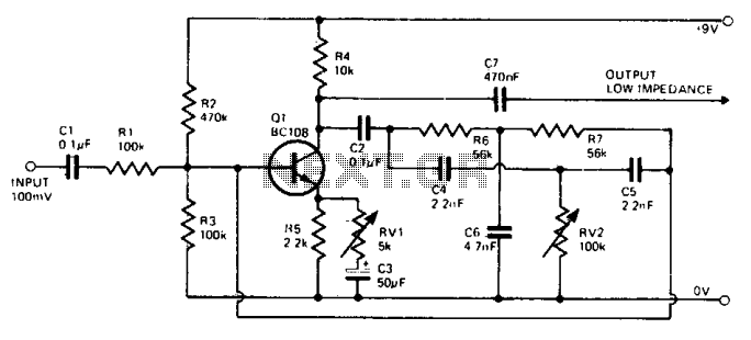
This simple circuit generates narrow pulses at a frequency of approximately 700-800 Hz. The pulses, which contain harmonics extending into the MHz range, can be injected into audio or radio-frequency stages of amplifiers and receivers for testing purposes. A...
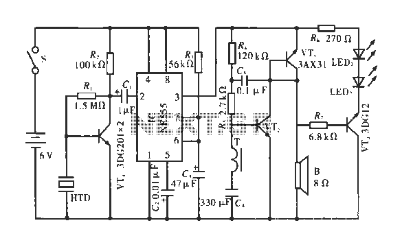
The circuit operates by detecting a clapping sound through a piezoelectric ceramic sensor, which converts the sound into an electrical signal. This signal is then amplified by the transistor VT1 and fed through a coupling capacitor C1 to the...

This is a two-zone alarm system featuring automatic exit, entry, and siren cut-off timers. It can be activated by standard normally-closed input devices, such as magnetic reed contacts, foil tape, and passive infrared sensors (PIRs). The circuit operates on...

This is an application circuit for calibration known as a high voltage AC calibrator circuit. A key aspect of sine wave oscillator design is the stable control of amplitude. In this circuit, the amplitude is stabilized through servo control,...

The TEA5551T monolithic integrated radio circuit can be utilized to design an AM radio receiver circuit intended for portable use with headphones. This circuit incorporates all necessary components for a complete AM radio receiver, including a fully integrated AM...
The wah-wah effect is created when specific frequencies are amplified more than others. The fundamental circuit consists of a phase shift RC oscillator. Negative feedback is implemented by returning a portion of the signal to the base. During initial...
Warning: include(partials/cookie-banner.php): Failed to open stream: Permission denied in /var/www/html/nextgr/view-circuit.php on line 713
Warning: include(): Failed opening 'partials/cookie-banner.php' for inclusion (include_path='.:/usr/share/php') in /var/www/html/nextgr/view-circuit.php on line 713