
Remote Solar LED light

The circuit described involves a solar-powered LED light that operates using the energy harvested from sunlight through a solar photovoltaic cell. The core components of this circuit include the solar panel, a white LED, and a current-limiting resistor. The solar panel generates direct current (DC) when exposed to light, and its output voltage is typically around 3.7V when sufficient illumination is present.
The LED is a key component that emits light when current flows through it. It is essential to match the output current of the solar cell with the current rating of the LED to ensure optimal performance and prevent damage. The solar panel's output is characterized by a maximum current rating, which should align with the LED's tolerance to avoid overcurrent situations.
In scenarios where the solar panel generates more than 20mA, a series resistor is recommended to limit the current flowing to the LED. This resistor acts as a protective measure, ensuring that the LED does not exceed its maximum current rating, which could lead to overheating and failure. A commonly suggested value for this resistor is 50 ohms with a power rating of 1/4 watt, which is typically sufficient to handle the excess current while maintaining the desired brightness of the LED.
The circuit's operation can be summarized as follows: when sunlight strikes the solar panel, it generates a voltage that turns on the LED as long as the voltage exceeds 3.7V. The LED, in turn, regulates the voltage across the circuit, ensuring that it does not exceed this threshold. The inclusion of the series resistor further stabilizes the circuit, promoting longevity and reliability in outdoor applications. This design is particularly suitable for remote lighting solutions, where conventional power sources are not feasible.The remote solar powered LED light takes advantage of the current limited nature of solar photovoltaic cells. If light shines on the solar array, current will flow through the circuit. For a typical size of solar cell, there is a maximum current that can be produced. The maximum solar cell current is simply matched to a value of current that the LED can handle. If there is enough light to raise the solar panel`s voltage above around 3.7V, the white LED will light up.
The LED regulates the maximum voltage across the circuit to around 3.7V. If the solar panel that you use produces more than 20ma, it may be necessary to insert a series resistor between the LED and the solar panel to prevent the LED from burning out. A 50 ohm 1/4 watt resistor is probably about right for the job, the exact val 🔗 External reference
Related Circuits
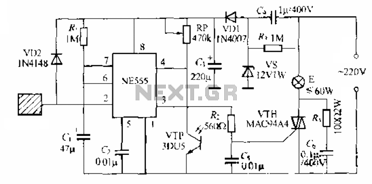
The circuit utilizes a NE553 automatic light sensor composed of 55 groups, allowing lights to turn on when individuals are present and turn off when they leave. The power supply includes VD1, vS, and C, with a 12V DC...
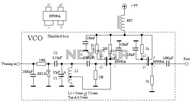
The VCO is based on a Hartley oscillator. The frequency is determined by L1 and capacitor C1. The tuning voltage will change the capacitance in the varactor BB132 which will change the oscillation frequency. The value of capacitor C2...
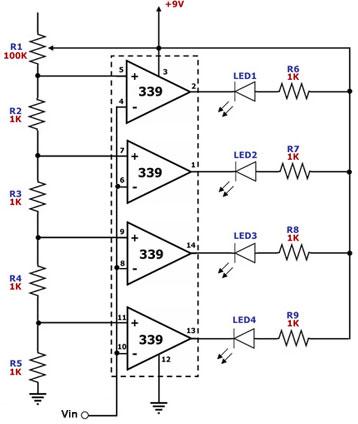
This circuit is designed as a simple LED bar graph voltmeter. Each operational amplifier in the LM339 quad package functions as a comparator, comparing the input voltage (Vin) to a series of fixed voltage levels that are proportional to...
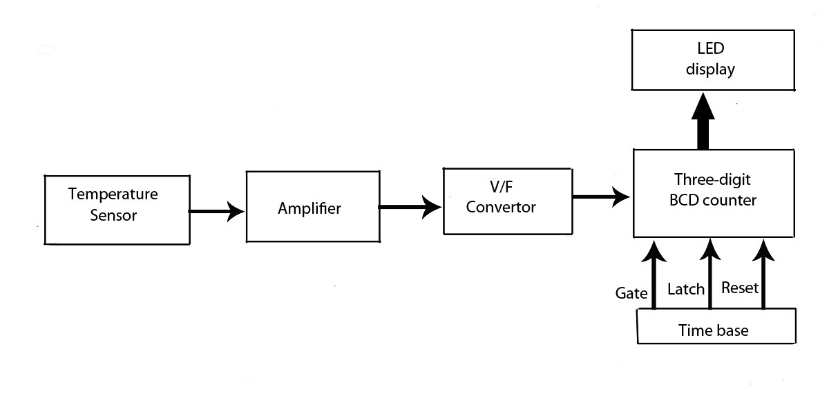
This verified project provides an idea, circuit, and operation of the LED display temperature indicator. It features a digital temperature indicator utilizing a voltage-to-frequency (V/F) converter, along with various electronic projects. The LED display temperature indicator is designed to provide a...
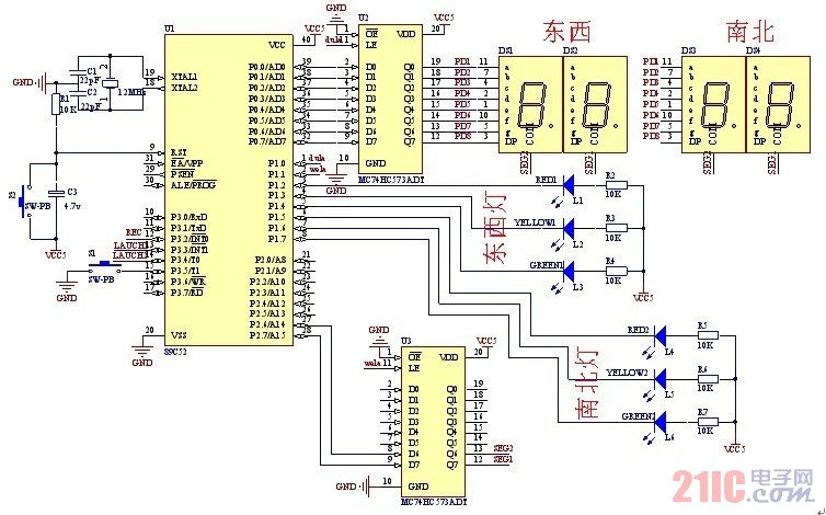
A steady, flexible, and convenient traffic light control system is essential for effective traffic management. In practice, many traffic lights operate on a time interval basis. This design allows for the adjustment of switching times for traffic lights during...
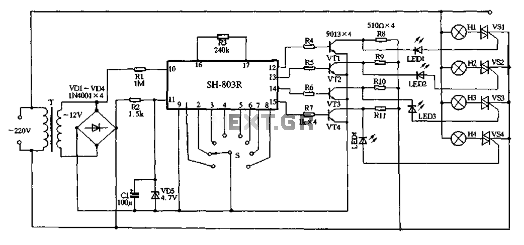
22V AC is supplied through thyristors VSl to VS4 for lighting control. The current is routed through transformer T, followed by rectification using diodes VD1 to VD4, and regulated by VD5 to provide a filtered output of approximately 4.7V...