
Advanced LED Temperature Indicator
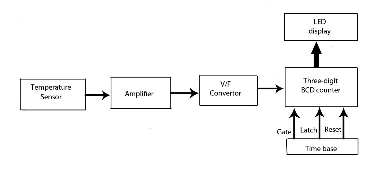
The LED display temperature indicator is designed to provide a clear visual representation of temperature readings. The circuit typically includes a temperature sensor, such as a thermistor or an LM35 temperature sensor, which converts temperature into an electrical signal. This signal is then processed by a voltage-to-frequency converter, which transforms the voltage output from the sensor into a frequency signal proportional to the temperature.
The frequency output can be fed into a microcontroller or a frequency counter that interprets the signal and drives an LED display, allowing users to read the temperature in real-time. Additional components may include resistors, capacitors, and a power supply unit to ensure stable operation of the circuit.
In terms of assembly, the circuit can be constructed on a breadboard for prototyping, with careful consideration given to the layout to minimize noise and interference. Proper calibration of the system is essential to ensure accurate temperature readings, which may involve adjusting the V/F converter settings based on the characteristics of the chosen temperature sensor.
This project serves as an educational tool for understanding the principles of temperature measurement and digital display technology, making it suitable for both hobbyists and students in electronics.this verified project provide idea, circuit and working of the system LED display temperature indicator. Digital temperature indicator.using V/F converter.various electronics project. 🔗 External reference
Related Circuits
The circuit was designed to provide an indication before a 12 V lead-acid battery reaches a discharged state using an LM723 voltage regulator and a positive NPN standard voltage. The circuit utilizes the LM723 voltage regulator, which is well-suited for...

Frequent use of direction indicators is essential for lane changes while driving on motorways. This is typically achieved by maintaining pressure on the indicator switch. The operation of direction indicators, commonly known as turn signals, is crucial for safe driving,...

An electret microphone feeds a bandpass filter circuit (IC1A), which subsequently drives a comparator. This comparator activates Q1, a switch that conducts when audio signals from IC1B cause D1, C4, R6, and R7 to bias it ON. The circuit begins...

This LED thermometer is designed for in home use, to read temperatures between about 60 and 78 degrees Fahrenheit. It is based around a precision temperature sensor IC, the LM34DZ. This sensor require no calibration and can measure temperatures...

In this circuit, the intensity of the LED varies in a ramping fashion. The circuit comprises three integrated circuits: two 555 timer ICs and one LM393 operational amplifier. IC1 and IC2 are configured as oscillators to generate frequencies of...

The current source created by Q1 in combination with capacitor C1 determines the duration of the ramp. As the positive DC voltage at the gate varies, the peak point firing voltage of the Programmable Unidirectional Thyristor (PUT) is altered,...