
Voltage Controlled Oscillator with BF990A

The Voltage Controlled Oscillator (VCO) described utilizes a Hartley oscillator configuration, which is characterized by its ability to generate oscillations at a frequency determined by the inductance (L1) and capacitance (C1). The inclusion of a varactor diode, specifically the BB132, allows for frequency modulation through the application of a tuning voltage. This tuning voltage alters the capacitance of the varactor, thereby enabling dynamic frequency adjustment.
Capacitor C2 plays a critical role in defining the tuning range of the VCO. By selecting a larger capacitance value for C2, the frequency deviation in response to the tuning voltage is increased, allowing for broader tuning capabilities. The circuit employs two dual-gate FETs; the first functions as the Hartley oscillator, while the second serves as an amplifier. The amplifier FET provides a gain of less than one, but it increases the output current without imposing a load on the oscillator, ensuring stable oscillation.
The output amplitude of the VCO is influenced by both the frequency of oscillation and the number of turns in the inductor L1. Adjustments to the gate voltage (g2) of the first FET can be made to set the desired output amplitude. Additionally, incorporating a resistor to ground can attenuate the output amplitude as needed. The schematic indicates that g2 is connected to Vcc through a resistor (R1), which maximizes gain.
Testing with different coil configurations has demonstrated the impact of inductor turns on performance. The inductor L1 has a consistent diameter of 7.2mm, with variations in the number of turns (3, 4, and 5) evaluated for their effects on amplitude and frequency characteristics. It is noted that during testing, the varactor was temporarily removed, making the tuning range reliant solely on C1.
For optimal performance, connecting an oscilloscope to the output is recommended. Should the oscillator produce a low amplitude signal, adjustments to the tap point on the inductor may be necessary. Constructing multiple coils with varying tap points allows for comparative testing to determine the most effective configuration. The VCO is capable of producing an output amplitude of approximately 200 mVRMS at a frequency of 100 MHz, illustrating its functionality within the desired operational parameters.The VCO is based on a Hartley oscillator. The frequency is determined by L1 and capacitor C1. The Vtuning voltage will change the capacitance in the varactor BB132 wich will change the oscillation-frequency. The value of capacitor C2 will determine how much the frequency can be changed by the tuning voltage.
The larger value the more the frequency will change. This VCO is based on two dual-gate FET. First FET is a Hartley oscillator where the frequency is determined by the value of L1, C1, C2 and the varicap diod. C2 set the span of the VCO. The second FET is just an amplifier. The gain is less than 1, but the current will be higher and the oscillator will not be loaded. The output amplitud changes depending on the frequency and how many turns there is on L1. By changing the voltage on g2 at FET1 you can set the amplitud. By adding a resistor to ground you will lower the amplitud. In this schematic I have conected g2 to Vcc (through R1) wich will give the highest gain. I have made some test with different coils. The diameter of L1 is the same 7.2mm but I have changed the turns to 3, 4 and 5. The diagram at the right shows the Amplitud and the frequency. You can also se the range of this VCO. During the test the varicap was removed so the tuning range is set by C1. The best way to get the oscillator work is to attach a oscilloscop to the output. If the amplitud of the oscillator is low, you must move the tap-point a bit. The best way is to make 3-4 coils with the tap-point at different places and test each coil before you decide wich one you will use. The amplitud from my VCO is about 200mVRMS at 100MHz. 🔗 External reference
Related Circuits
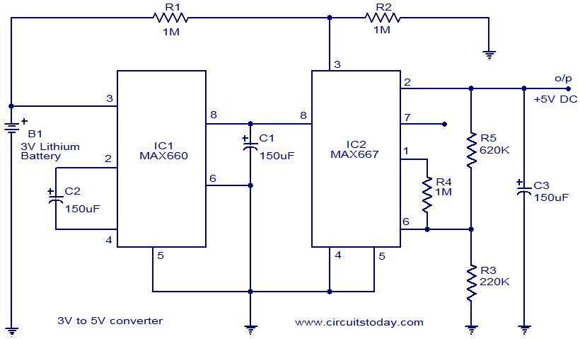
Voltage converter circuit diagram for converting 3 volts to 5 volts using CMOS monolithic ICs MAX660 and MAX667, which functions as a positive voltage regulator. The voltage converter circuit utilizes the MAX660 and MAX667 integrated circuits to step up a...
The circuit illustrated in the diagram allows for the generation of a negative voltage without utilizing integrated circuits. It employs five n-p-n transistors controlled by a TTL clock operating at approximately 1 kHz. When the clock signal is high,...
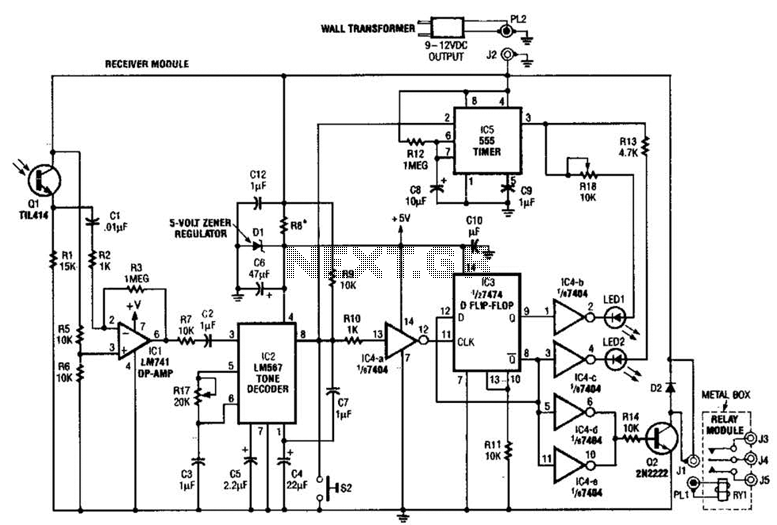
Useful for A/B control, the IR receiver shown controls a relay from an infrared beam that has a pulsed tone-modulated signal. Q1 is the photo receptor feeding op amp IC1, tone decoder IC2, and flip-flop IC3. IC5 turns off...
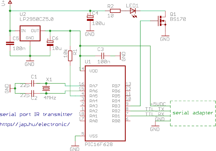
This is a programmable infrared (remote control) transmitter, which can be controlled from a PC serial port. It is capable of sending many remote control formats, including the Philips RC-5 standard. Exact formats with the timing parameter names are...
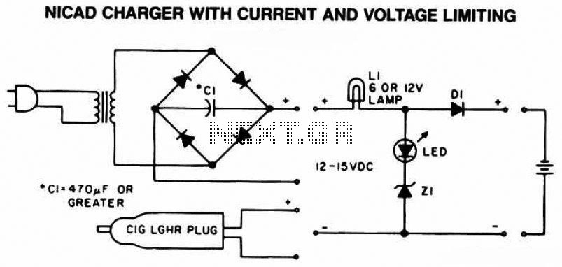
The following diagram is the schematic of a Ni-CAD battery charger circuit, which includes current and voltage limiting features to extend the battery's lifespan. The lamp L1 will illuminate brightly, and the LED will be off when the battery...
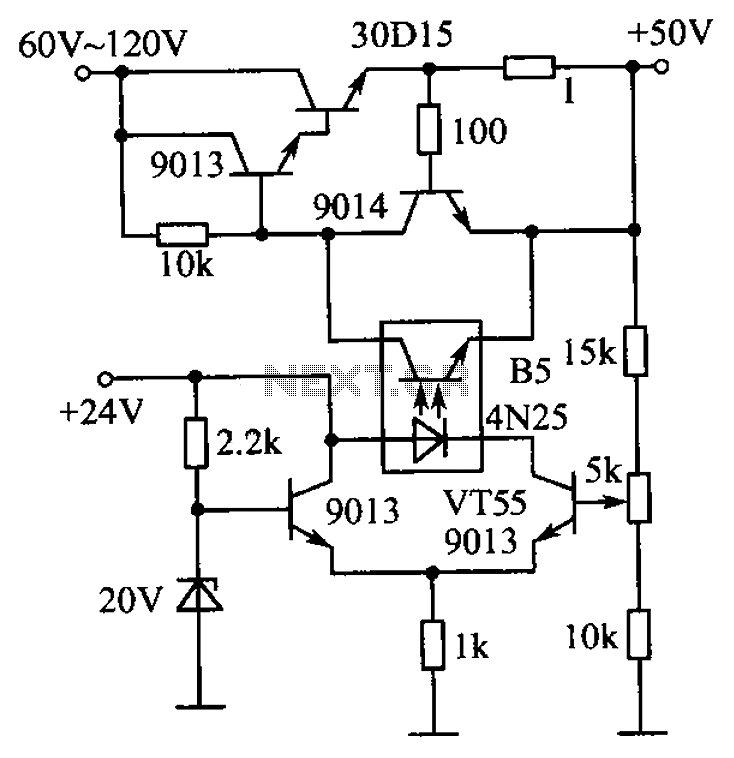
The circuit is illustrated. A standard driving transistor requires a higher breakdown voltage transistor (such as the FIG driving tube 9013). As the output voltage rises, the bias on VT55 increases, leading to an increase in the forward current...