
Remote tuning transmitter
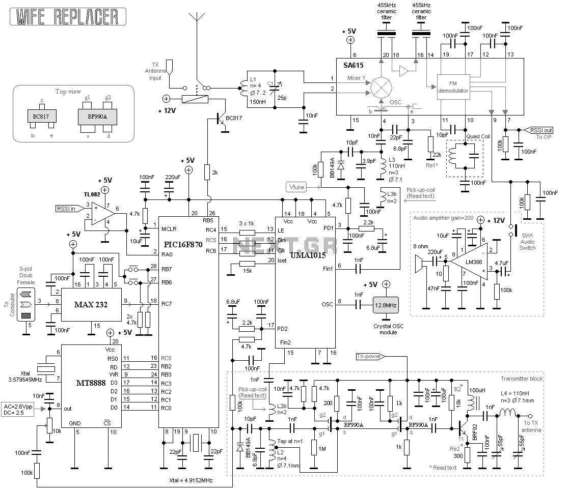
The described project features a wide-range receiver and transmitter system designed for tuning homebrewed transmitters, particularly in the 88-150 MHz range for reception and 125 MHz for transmission. The system incorporates a UMA1015 PLL synthesizer, which provides frequency stability and facilitates easy tuning through two separate PLL units.
The antenna receives RF signals that are directed to the receiver. The receiving frequency is controlled by a Voltage Controlled Oscillator (VCO), which operates between 88 and 150 MHz. The VCO's tuning voltage is regulated by PLL synthesizer A, which also monitors the VCO frequency to maintain optimal performance. A microcontroller, specifically the PIC16F870, is employed to program both synthesizers and manage the overall operation of the system.
The receiver utilizes the SA615 integrated circuit, which includes a mixer, oscillator, intermediate frequency (IF) amplifier, and demodulator. The antenna is connected to a narrow bandpass LC filter (L1 and C1) designed to reject unwanted frequencies while optimizing antenna performance within the specified frequency range. After filtering, the RF signal is processed by the SA615, which mixes the incoming signal and prepares it for demodulation. Two ceramic filters are employed at 455 kHz to further eliminate undesired frequencies before the FM demodulation stage.
The internal oscillator of the SA615, configured as a Colpitts oscillator, employs a coil (L3) and a varicap diode (BB149A) to achieve voltage-controlled oscillation. The varicap's capacitance varies with the applied voltage, allowing for fine-tuning of the oscillator frequency. The voltage tuning signal (Vtune) is sourced from the PLL synthesizer, varying between 0 to +5V to adjust the oscillator frequency as needed.
To enhance the oscillator's performance, a secondary coil (L3b) is placed in proximity to L3 to couple energy and feed the synthesizer frequency input (Fin 1). This design minimizes component count while ensuring reliable frequency probing. The system also includes an audio amplifier to allow for audible signal output from the receiver, facilitating practical testing and evaluation of the transmitter's performance.
Overall, this project demonstrates a comprehensive approach to building a versatile RF receiver and transmitter system, addressing common challenges in homebrewing and providing a functional solution for effective tuning and operation.This project consists of a wide range receiver and one transmitter. Together they will form a unit which will help you tuning your homebrewed transmitter. The most difficult part of homebrewing is the tuning part of the transmitters. How should I design and tune the output filter of my transmitters? Well, you can use a 50 ohm dummy load and tune the transmitter for best performance. When you connect your antenna, which probably won't have 50 ohm resistive load and you will lose lot of power. Okay, you have 100W so what! You will still be able to transmit to your neighbour 1km away. 88-150MHz Receiver, 125MHz transmitter. Both the receiver and the transmitter frequency is set by a frequency PLL synthesizer. This will give very good stability and easy tuning. In this case I use a UMA1015 synthesizer. This synthesizer do have two separate PLL units. At top of the blockdiagram you will find the antenna. The RF signal enter the antenna and is then switched to the receiver (green box). The receiving frequency of this box is set by a VCO (Voltage controlled Oscillator) pink box. This VCO can be set from 88 to 150MHz by a voltage (PD) coming from the PLL synthesizer A (left yellow box). The synthesizer also probe the VCO frequency (Fin RX) to regulated the PD voltage of the VCO (pink box).
The synthesizer A and B is programmed by a micro controller PIC16F870. When the receiving frequency is set, the CPU will measure the RSSI (Relative Signal Strength Indicator) voltage by its internal A/D converter. The RSSI signal is a voltage from 0 - 5V. The CPU will transform the value to 3 digits. The CPU then set the Synthesizer B, so that the VCO (orange box) oscillate at 125MHz. Also here the synthesizer probe the VCO frequency (Fin TX) to regulate the PD voltage of the VCO. The output power of this VCO is a few milliwatt. The CPU then switches the antenna-switch so that the antenna is connected to the transmitting VCO. The 3 digits is then sent to the DTMF unit which will modulate the transmitter and the DTMF signals is sent.
The antenna-switch then go back to the receiver and everything start to repeat again. Let's focus at the receiver part first. The receiver is build around the SA615 circuit. This circuit has everything inside, mixer, oscillator, IF amplifier and demodulator. The antenna is connected to a LC filter L1 and C1. This filter is a narrow bandpass filter to reject all unwanted frequencies. This filter will also tune the antenna for best performance. The filter can be set to cover the band of 88-150MHz. The rf signal then enter the SA615 and into the mixer. Two ceramic filter is connected before the FM demodulator. The ceramic filter is at 455kHz and will reject all unwanted frequencies from the mixer. The SA615 circuit has an internal oscillator which is internally connected to the mixer. The oscillator can be found a pin 3 and 4. The oscillator is a collpit type and the oscillating part is L3 and the varicap diod BB149A. At pin 4 you can find a coil L3 parallel with a capacitor of 3.9pF. How to make this oscillator voltage controlled? Parallel with the 3.9pF capacitor you will find a varicap diod. The capacitans of this diod is dependent of the voltage over it. So, by applying a voltage to the varicap the internal capacitance will change and so will the resonance frequency. The purpose of the 10pF serie capacitor is to remove the VtuneDC-voltage. By changing the Vtune voltage to the varicap the frequency will slide a few MHz. The Vtune is coming from PD1 (pin 3) at the PLL synthesizer UMA1015. The voltage is from 0 to +5V and this voltage can change the oscillator frequency a few MHz. At pin 3 you will find a resistor Re1. This resistor is added to raise the oscillator current. Pic at right show you the L3 coil. I have put some glue on the coil to make it stable for vibrations. In line with the coil L3 is another coil named L3b. This coil has two turns (no critical dimensions)and it absorb a fraction of the energy from the main oscillator coil L3.
The purpose of this second coil, is to feed the synthesizer frequency input Fin 1 (pin 6). The frequency inuput is so sensitive that you only need a 1-2 tune coil close to L3 to pick up the oscillation frequency. Other way to probe the oscillator which I used in onther PLL construction is to use a dual gate FET to probe the oscillator.
I think this new way works better and needs less components. By changing the distance from the main oscillator coil L3 and the pick up coil L3b, you can easy adjust the input amplitude to the PLL synthesizer. In practical way I advice you to place the L3b close to L3 and see how well it works. I had to move L3b (pick-up-coil) a bit away from L3, because it gave to strong signal. See the photo at right. In my schematic below I have also added an audio amplifier to the receiver so you can hear the signal from the testing object.
I will go into all details later. 🔗 External reference
Related Circuits
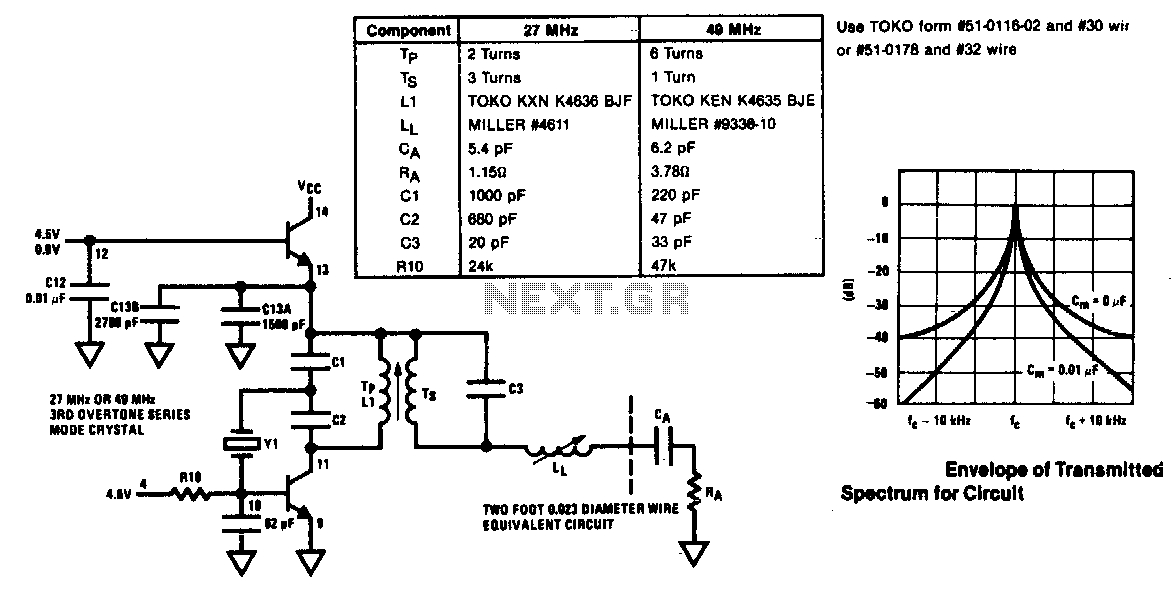
The modulator and oscillator comprise two NPN transistors. The base of the modulator transistor is powered by a bidirectional current source, with the voltage range for the high condition restricted by a saturating PNP collector connected to the pin...
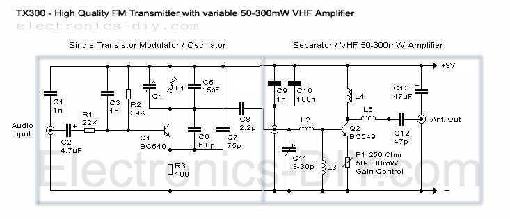
Here it is a brand new TX300 FM transmitter. The amplifier has exactly the same architecture as TX500 with the difference that TX300 has only one stage variable VHF amplifier. It is a cute schematic that was made for...
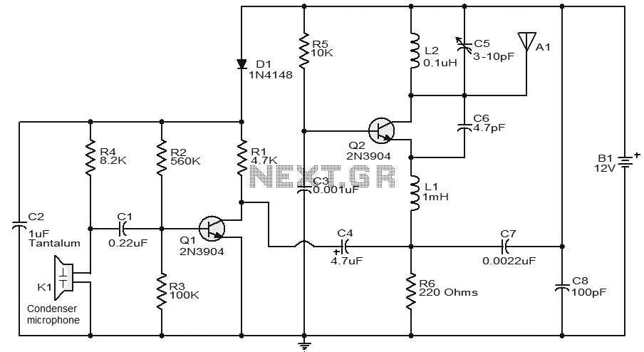
This circuit features a very stable and simple FM transmitter design. This transmitter can achieve a range of approximately 200 meters when properly matched. The FM transmitter circuit typically consists of several key components: an oscillator, modulator, amplifier, and antenna....
The first resistor on the left in the schematic is labeled as 68k. This value may change based on the microphone used. In this instance, a microphone from Digi-Key with a 1.5k output impedance was utilized, leading to the...
The voice circuits discussed in this section operate such that during daylight or in bright conditions, the voice-activated switch remains off, preventing the lamp from lighting. Conversely, in low-light conditions or at night, the sound control switch is activated....
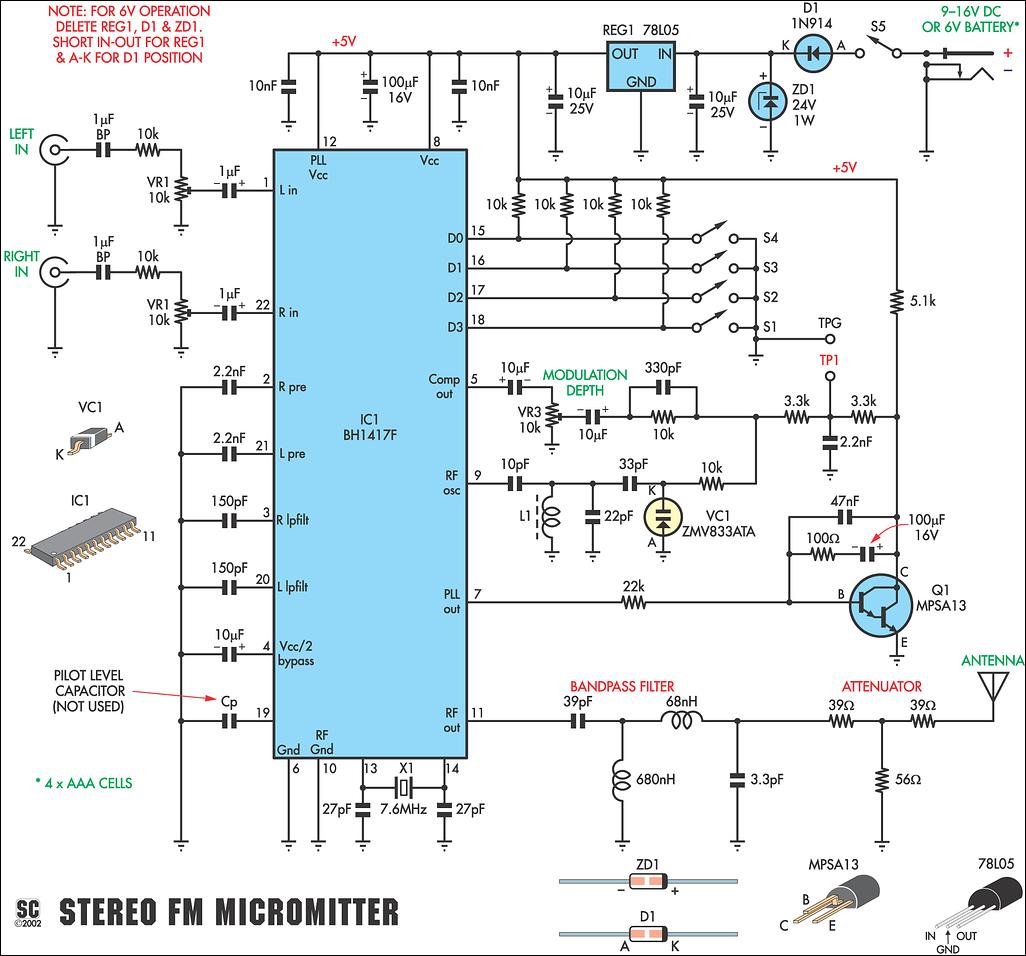
This new stereo FM Micromitter is capable of broadcasting good quality signals over a range of about 20 meters. It is ideal for broadcasting music from a CD player or any other source so that it can be picked...