
300mW FM Transmitter
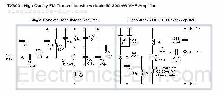
The TX300 FM transmitter circuit is designed to provide a simplified solution for FM transmission, particularly suitable for personal use in small areas such as homes and yards. The circuit architecture mirrors that of the TX500, with the notable modification of employing a single-stage variable VHF amplifier, which streamlines the design and reduces component count.
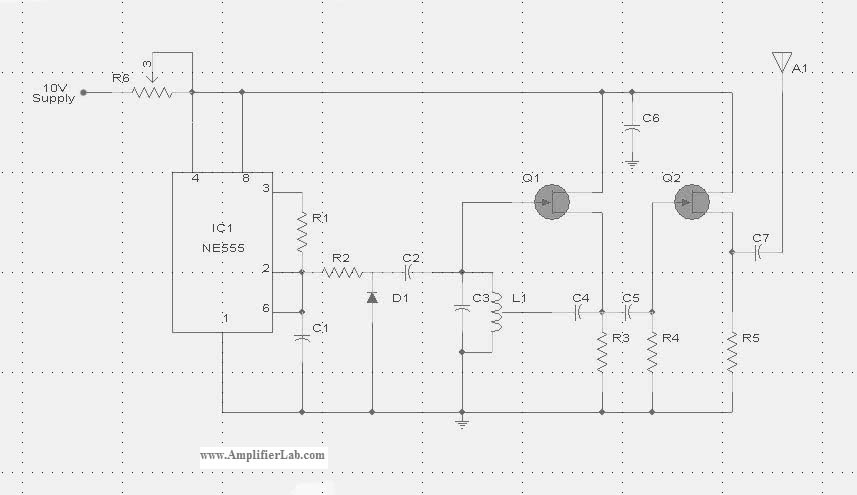
The transmitter operates by utilizing a VHF amplifier (Q2) and an oscillator (Q1). The gain control potentiometer (P1) allows users to adjust the output power and transmission distance, providing flexibility based on the user's needs. This feature is particularly advantageous for those who wish to modulate their audio signals with varying ranges, accommodating different environments and requirements.
In cases where enhanced transmission power is desired, the circuit allows for the substitution of Q2 with higher-power transistors such as the 2N4427 or 2N3866. However, this modification necessitates the replacement of P1 with a fixed resistor to manage the increased current demands of the more powerful transistor.
The circuit is designed on a separate board, facilitating integration with a smaller printed circuit board (PCB) for compact assembly. This modular approach enhances usability and allows for easier adjustments and testing. Additionally, a power meter is incorporated into the design to measure the output power from both the VHF amplifier (Q2) and the oscillator (Q1), providing essential feedback for tuning and optimization.
The coils used in the TX300 are identical to those in the TX500, ensuring compatibility and performance consistency across both models. This design choice further simplifies the construction process, as users can leverage existing components from the TX500 for their TX300 builds. Overall, the TX300 FM transmitter represents an efficient and user-friendly option for personal FM broadcasting.Here it is a brand new TX300 FM transmitter. The amplifier has exactly the same architecture as TX500 with the difference that TX300 has only one stage variable VHF amplifier. It is a cute schematic that was made for all of you who wanted something even simpler than TX500 and with not as many necessary parts.
It is a perfect circuit for transmitting your music around the house and yard. Interesting feature is a gain control P1 that lets you adjust your desired output power and distance. If in case you want to replace Q2 with more powerful transmitter like 2n4427 or 2n3866 you will have to replace P1 with a resistor due to the higher necessary current.
For much more info go to TX500`s page. This power meter will let you test both the output power of Q2 (VHF amp) and Q1 (oscillator). Circuit is now on the separate board so you can fit the main circuit of the smaller PC board. Coils: TX300 uses exactly the same coils as TX500 w 🔗 External reference
Related Circuits
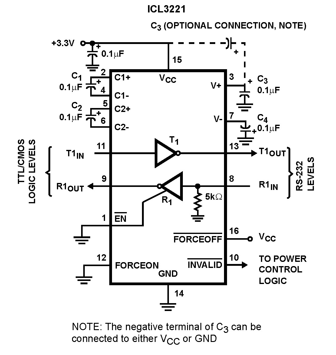
The Intersil ICL32XX devices are powered by 3.0V to 5.5V and function as RS-232 transmitters and receivers, complying with EIA/TIA-232 and V.28/V.24 specifications, even at a supply voltage of 3.0V. These devices are designed for applications such as PDAs,...
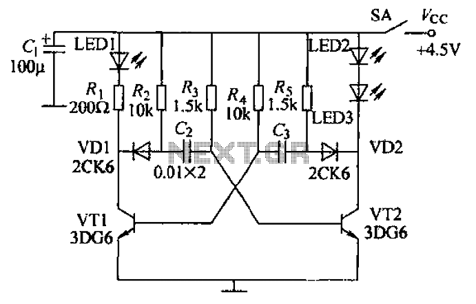
Transistors VT1, VT2, and associated RC components are configured to form a multivibrator. The multivibrator operates with resistors Ra and R4 serving as base bias resistors for VT2 and VT1, respectively. When the switch SA is closed after applying...
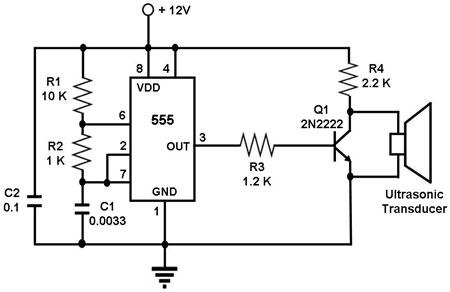
The circuit utilizes a 555 timer integrated circuit (IC) configured as an astable multivibrator, which generates a continuous signal at a specific frequency as long as its reset pin (pin 4) is held high. The ultrasonic transducer employed in...
L2 RFC (resistance 1MOhm with an inductor wrapped around it made from fine isolated wire. Scratch the inductor and connect it to the resistance, creating a parallel L-R circuit.) With C7 and C8, we adjust the resistance of the...
The circuit diagram of the Radio Collar Transmitter is presented here. This circuit is based on the NE555 integrated circuit, which serves as the central component. The Radio Collar Transmitter circuit utilizes the NE555 timer IC to generate a modulated...
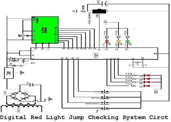
A digital red light jump checking system with an RF transmitter. This project allows for the tracking of vehicles that run red lights by capturing their license plate numbers and the time of the violation. The digital red light jump...